


Tech
The Symphony of Connectivity: Understanding Ethernet Devices
Welcome to the symphony of connectivity, where every note is played by Ethernet devices. In this digital era, where technology orchestrates our daily lives, understanding how these devices harmonize to keep us seamlessly connected becomes vital. From routers and switches to modems and network adapters, each instrument plays its unique role in creating an enchanting symphony that allows us to surf the web, stream movies, and communicate effortlessly. So join us as we dive into the world of Ethernet devices – a captivating ensemble that keeps our modern world humming with connectivity!

In the fast-paced and interconnected digital era, the symphony of connectivity plays a pivotal role in our daily lives. At the heart of this harmonious symphony lie Ethernet devices, conducting a seamless flow of data, orchestrating communication, and ensuring that we stay connected with the world. In this article, we embark on a captivating journey to unravel the enigma behind these remarkable Ethernet devices – the Network Interface Device (NID), Network Termination Unit (NTU), and more.
I. Introduction
In a world where connectivity has become the lifeblood of our daily activities, Ethernet devices emerge as the unsung heroes of modern communication. They are the architects of interconnected networks, paving the way for seamless data transfer and smooth communication. Let’s delve into the realm of Ethernet devices and explore their magical capabilities that enable us to stay in touch with the world at our fingertips.
II. Unraveling the Enigma of Network Interface Devices (NID)
Our symphony begins with the mysterious Network Interface Device (NID), a vital component in the realm of telecommunications. Acting as a guardian between the service provider’s network and the customer’s premises, the NID ensures a safe and efficient flow of communication. It stands as a sentinel outside our buildings, where the service provider’s network links to our internal wiring. The NID is the gateway through which telecommunication services like internet, telephone, and digital TV enter our abode.
III. Venturing into the Enchanted Realm of Network Termination Units (NTU)
Beyond the boundaries of conventional communication lies the enchanted world of fiber-optic networks. In this realm, the Network Termination Unit (NTU) takes center stage. Gracefully terminating the fiber-optic cable, the NTU performs a mystical alchemy, converting optical signals into electrical ones. This transformation allows seamless integration with the customer’s internal network equipment, unlocking the wonders of high-speed data access. With its wisdom in error correction and signal regeneration, the NTU ensures the data journey remains filled with integrity and brilliance.
IV. The Symphony of Ethernet Devices: Harmonizing Data Flow
As the symphony unfolds, we encounter a dazzling ensemble of Ethernet devices, each playing a unique role in the orchestration of data flow.
- Ethernet Switches: The Master Conductors
Imagine a local area network (LAN) as a grand concert hall, where Ethernet switches take the center stage as the master conductors. Each device connected to an Ethernet switch becomes a virtuoso, with its dedicated communication channel. The switches deftly navigate data packets through the most efficient paths, ensuring a melodious flow of data, free from congestion and delays.
- Ethernet Routers: Adventurous Explorers of Networks
In the vast kingdom of networking, Ethernet routers play the part of adventurous explorers, forging paths between LANs and wide area networks (WANs). Like skilled cartographers, they chart the best routes for data to traverse, transcending geographical boundaries and bridging distant realms. Their intelligence in network topology and traffic conditions makes every data journey an epic tale of connectivity.
- Ethernet Adapters: The Magicians of Connection
Enter the enchanting world of Ethernet adapters, the magicians of connection. These mystical network interface cards (NICs) enchant our devices, granting them access to the secrets of the network. With their spellbinding abilities, they enable seamless communication and data exchange among our beloved devices, weaving a tapestry of connectivity in the digital realm.
- Ethernet Extenders: The Time Travelers of Networking
When distance seems like an insurmountable obstacle, Ethernet extenders come to the rescue as the time travelers of networking. With their otherworldly prowess, they extend the reach of network connections beyond standard limitations, bridging gaps between far-off locations and connecting devices in remote realms.
V. The Future Symphony of Connectivity: Advancements and Outlook
As technology pushes the boundaries of innovation, the symphony of Ethernet devices continues to evolve and adapt. Emerging technologies promise even greater speed, reliability, and efficiency in data communication. The future prospects of NID, NTU, and Ethernet devices hold the promise of building interconnected, reliable, and high-speed networks for a world that thrives on seamless connectivity.
The symphony of connectivity, led by the magical prowess of Ethernet devices, will continue to shape our digital experiences. From the guardianship of NID to the enchantment of NTU and the brilliance of Ethernet switches, routers, adapters, and extenders, these devices unite to create a harmonious symphony of communication. With the quest for seamless connectivity propelling us forward, the future of networking and communication holds the promise of a world forever connected in a symphony of digital dreams.
FAQs
- Q: What is the role of a Network Interface Device (NID) in telecommunications? A: The Network Interface Device (NID) serves as the boundary between the service provider’s network and the customer’s premises. It allows telecommunication services to be delivered to the customer’s location and acts as a protective boundary, separating the responsibilities of the service provider and the customer.
- Q: Where is the Network Interface Device (NID) typically installed? A: The NID is usually located outside a building, where the service provider’s network connects to the customer’s internal wiring. It serves as the entry point for telecommunication services to the customer’s location.
- Q: What does the Network Termination Unit (NTU) do in fiber-optic networks? A: The Network Termination Unit (NTU) plays a crucial role in fiber-optic connections. It terminates the fiber-optic cable and converts the optical signal to an electrical signal, allowing seamless integration with the customer’s internal network equipment.
- Q: What are the benefits of using the Network Termination Unit (NTU) in fiber-optic networks? A: The NTU provides reliable and fast data communication through fiber-optic networks. By converting optical impulses to electrical signals, typical networking equipment like routers and switches can better interpret and process the data. The NTU also enables error correction and signal regeneration, ensuring data integrity and quality.
- Q: How do Ethernet switches contribute to network communication? A: Ethernet switches act as master conductors in local area networks (LANs), allowing direct communication between devices. Each device connected to an Ethernet switch has its own dedicated communication channel, ensuring fast data transfer and reducing network congestion.
- Q: What role do Ethernet routers play in a network? A: Ethernet routers interconnect networks, enabling seamless communication between LANs and wide area networks (WANs). They determine the best path for data to travel between networks, making intelligent decisions based on network topology and traffic conditions.
- Q: How do Ethernet adapters facilitate communication between devices? A: Ethernet adapters, also known as network interface cards (NICs), are essential for connecting devices like computers, servers, and printers to the network. They enable these devices to communicate with each other and access network resources.
- Q: What is the purpose of Ethernet extenders? A: Ethernet extenders are used to extend the reach of Ethernet connections beyond the standard distance limitations. They enable data transmission over longer distances, making them ideal for connecting devices in remote locations where running new network cables is impractical.
- Q: Why are Ethernet devices crucial for modern networking? A: Ethernet devices form the foundation of modern networking, enabling smooth data transmission and seamless communication within and between networks. Ethernet switches, routers, adapters, and extenders play essential roles in building reliable and efficient networks.
- Q: How will NID, NTU, and Ethernet devices shape the future of communication and networking? A: NID and NTU will continue to play critical roles in ensuring seamless communication between service providers and customers, especially with the increasing demand for high-speed data. Ethernet devices will continue to evolve and adapt to new technologies, enabling the development of interconnected, reliable, and high-speed networks for a connected world.

The long-term commercialization of complex software frameworks cannot rely on financial support alone. Emerging technology segments—ranging from cloud-native software layers to hardware-integrated medical instruments—face distinct operational constraints that defy uniform generalist strategies. Startups navigating the long validation timelines of clinical certifications or the severe code-hardening requirements of critical infrastructure defenses must align with specialized capital networks. If an early-growth company partners with generalist finance groups that lack deep industry insights, it faces significant risks of structural misalignment, missed validation deadlines, and premature failure within competitive international supply chains.
To minimize these market integration risks, institutional innovation pipelines are deploying a specialized, target-grouped enterprise software venture capital framework. Rather than spreading generalist funds thinly across unconnected industries, specialized models isolate individual investments within specific, highly technical verticals. This comprehensive analysis evaluates the structural scaling mechanics across high-barrier domains, outlines why cross-industry groupings require distinct advisory protocols, and details how targeted vertical incubation pathways insulate tech firms from broader macroeconomic market shifts.
Vertical Customization Across Specialized SaaS Platforms
Modern business systems are moving away from horizontal, general-purpose applications in favor of highly specialized, vertical-specific software solutions. Startups developing deep algorithmic tools for complex workflows, such as financial audit automation or high-performance data pipeline monitoring, require specialized infrastructure support from day one. These companies face unique go-to-market challenges, including complex technical evaluations and specialized data localization regulations.
Partnering with a specialized software venture capital firm portfolio structure tailored for these exact parameters resolves these structural challenges. By utilizing deep engineering benchmarks, dedicated investment networks accelerate the transition from initial deployment to predictable enterprise scale. This targeted alignment enables scaling software groups to clear technical review hurdles smoothly, helping them capture market share in competitive enterprise sectors.
Comparative Performance Metrics: Sector Stability and Scaling Success
Market evidence confirms that startups backed by specialized capital pools achieve substantially higher five-year survival and scaling rates than those relying on generalist finance networks. When investment groups apply deep domain expertise to high-barrier technological verticals, portfolio companies navigate complex regulatory frameworks and commercial onboarding tracks far more efficiently.
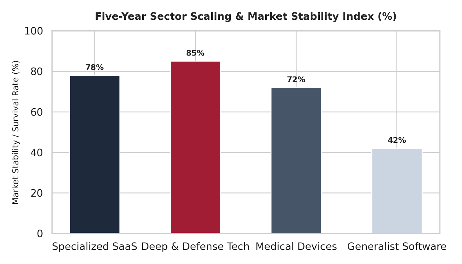
The chart below outlines the five-year operational stability index across primary specialized technical segments compared to generalist market alternatives:
Five-Year Sector Scaling & Market Stability Index Breakdown:
Deep & Defense Tech: 85%
Specialized SaaS: 78%
Medical Devices: 72%
Generalist Software: 42%
Specialized Navigation in Medical Device and Deep Tech Sectors
The operational demands of healthcare and engineering technology require highly specialized, domain-specific investment approaches. Developing complex hardware-software configurations requires navigating strict validation tracks, including exhaustive clinical trials and stringent data-security reviews. For instance, a startup pioneering advanced medical diagnostic tools faces long, complex development cycles that standard software investors are rarely equipped to evaluate.
To manage these intense validation demands, sophisticated investment strategies utilize dedicated medical device venture capital support pipelines. These groups combine regulatory advisory teams with deep engineering networks to guide products smoothly from prototype to clinical validation. This specialized model ensures absolute alignment between technical code structures and complex regulatory mandates, transforming early-stage technology into a stable driver of long-term commercial growth.
Conclusion
Securing sustainable global market share in highly technical software and hardware spaces requires a deliberate, domain-specific approach to venture financing. Relying on generalist capital loops introduces significant regulatory alignment risks and unpredictable development timelines. Utilizing a targeted, vertically grouped investment framework ensures that scaling companies possess the capital stability, technical insight, and enterprise access needed to dominate complex markets. As global data security regulations and corporate validation standards continue to tighten, aligning with specialized, expert-backed cybersecurity venture capital structures remains an essential prerequisite for scalable technological expansion.
Enterprise Software-as-a-Service (SaaS) web platforms manage highly complex digital environments. Because these sites use dynamic code frameworks, localized subdomains, gated resource hubs, and continuous product updates, they are highly prone to hidden technical errors. Issues like broken internal redirect loops, unmapped crawl paths, and slow JavaScript rendering can quickly harm search rankings. When search engine bots encounter these technical barriers, they reduce their crawl frequency, which leaves new product landing pages unindexed for weeks. For a fast-growing SaaS business, these technical blind spots can hurt customer acquisition speeds and lower long-term digital ROI.
To eliminate these infrastructure risks, successful tech companies treat technical optimization as a core engineering task. Running systematic, highly rigorous data audits allows operations teams to locate and resolve indexation bottlenecks before they impact organic traffic. This review details the technical benchmarks needed to pass an enterprise-grade audit, explains why clean site architecture affects crawl efficiency, and outlines the mechanical advantages that separate automated, real-time indexation tracking from basic manual site reviews.
Maximizing Crawl Budgets via Structural Health
Search engine crawlers allocate a limited amount of processing time—known as a crawl budget—to every website. On large SaaS platforms containing thousands of dynamic pages, a significant portion of this budget is often wasted on broken links, duplicate parameters, or unnecessary redirect loops. This fragmentation prevents core marketing pages and high-value conversion funnels from being indexed efficiently.
Passing a professional technical evaluation requires securing a clean, shallow crawl path that allows search bots to reach any page on the site within three clicks of the homepage. Incorporating a rigorous, data-driven framework like the one used in SEO Audits ensures that server errors and duplicate content paths are eliminated, maximizing the value of your search engine crawl budget.
Remediation Timeline: Compressing Search Bot Latency
When a site’s backend architecture is systematically cleaned of code bloat and unmapped loop strings, search engine spiders can re-index system modifications at a dramatically accelerated pace:
-
Pre-Audit Baseline: 18 Days indexation latency due to broken redirect lines and unmapped paths.
-
Wave 1 (Technical Corrections): 5 Days indexation latency achieved immediately after cleaning redirect chains and fixing server response blocks.
-
Wave 2 (GEO Alignment Framework): Less than 24 Hours re-indexing turnaround realized by generating static, clean schema maps.
Content Visibility Across Generative Engines
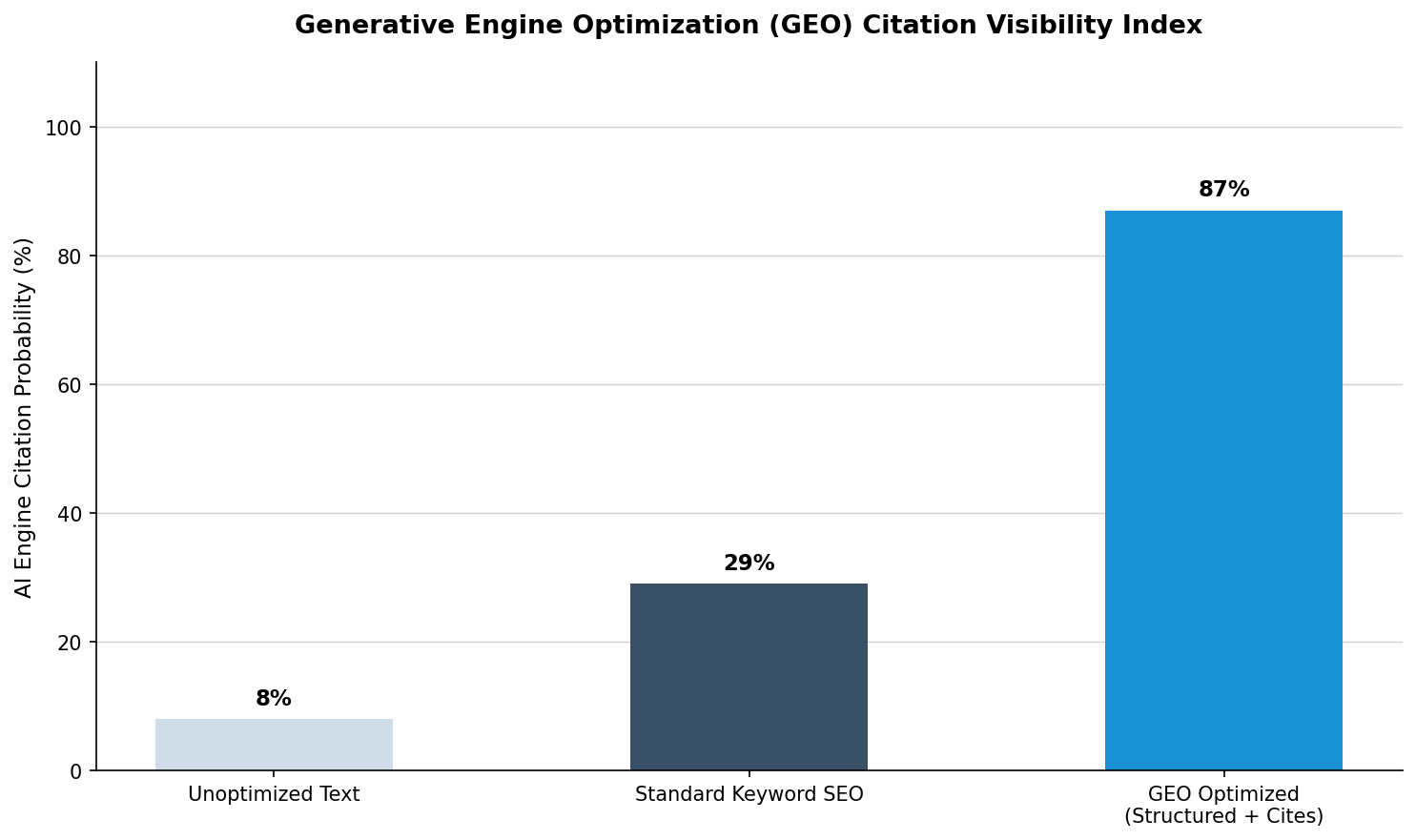
Beyond traditional text indexing timelines, backend code optimization directly establishes how effectively autonomous scrapers map context to serve conversational search platforms.
The visibility metric diagram below highlights the probability breakthroughs achieved when transitioning from legacy text formats into optimized data delivery architectures:
Optimizing Dynamic Frameworks for Modern Scrapers
Many modern SaaS platforms use JavaScript-heavy client-side rendering (such as React, Angular, or Vue) to build fast, interactive user interfaces. While this creates a great experience for human visitors, it often presents major challenges for search engine scrapers, which may fail to execute the underlying scripts correctly during their initial pass. This leaves behind a blank or partially rendered page that cannot be indexed accurately.
To fix this rendering gap, engineering groups must implement Server-Side Rendering (SSR) or dynamic pre-rendering configurations across their entire web presence. Combining these advanced server changes with optimized schema markup provides search engines with pre-built, instantly readable content. Following an expert, step-by-step framework for Technical SEO for SaaS Companies ensures that your digital infrastructure remains highly visible, turning technical perfection into a reliable engine for long-term organic growth.
Conclusion
Technical integrity forms the baseline of any successful enterprise digital expansion strategy. If a website possesses broken crawl links or unreadable script payloads, even the highest-quality content will fail to rank or find its way into AI responses. By approaching technical health as an engineering priority and executing systematic data updates, SaaS enterprises can build highly scalable, fast-loading platforms that lock down maximum search traffic natively.
The explosive growth of commercial generative AI has created a significant and urgent data protection challenge for modern information security officers. While employees look for ways to streamline workflows, they regularly paste sensitive proprietary files, internal product code, and regulated customer records directly into unapproved public Large Language Models (LLMs). Because these public consumer tools often use user inputs to retrain their core algorithms, proprietary corporate data can easily leak out, exposing companies to massive compliance risks, intellectual property theft, and regulatory non-compliance. When these activities happen without IT approval, it creates a major blind spot known as shadow AI.
To counter this hidden risk vector, security-conscious organizations are deploying specialized shadow AI detection utilities. Traditional web filters and old cloud access tools fail to spot these threats because they cannot evaluate the text context inside natural language data movements. Modern shadow AI monitoring platforms solve this by combining real-time web traffic audits with advanced semantic analysis, allowing companies to detect unauthorized AI tools instantly. This review looks at how shadow AI risks develop, why passive web blocking fails, and what operational features distinguish dedicated discovery engines from basic legacy filters.
The Realities of the AI Discovery Gap
To build an effective data protection strategy, enterprise teams must recognize that shadow AI introduces far greater risks than traditional unmanaged software usage (Shadow IT). Historically, Shadow IT involved employees downloading unauthorized chat apps or cloud storage tools. While this introduced security risks, the underlying corporate data remained static inside an isolated storage environment.
Shadow AI completely changes this risk equation. When an employee inputs data into an unapproved web model, that information is absorbed into an active machine learning system. This creates an environment where an AI visibility tool enterprise solution is required to run a full AI asset inventory security scan, identifying precisely which unsanctioned models are consuming corporate data before it is trained out to public systems.
Data Interception Latency Under Evaluation
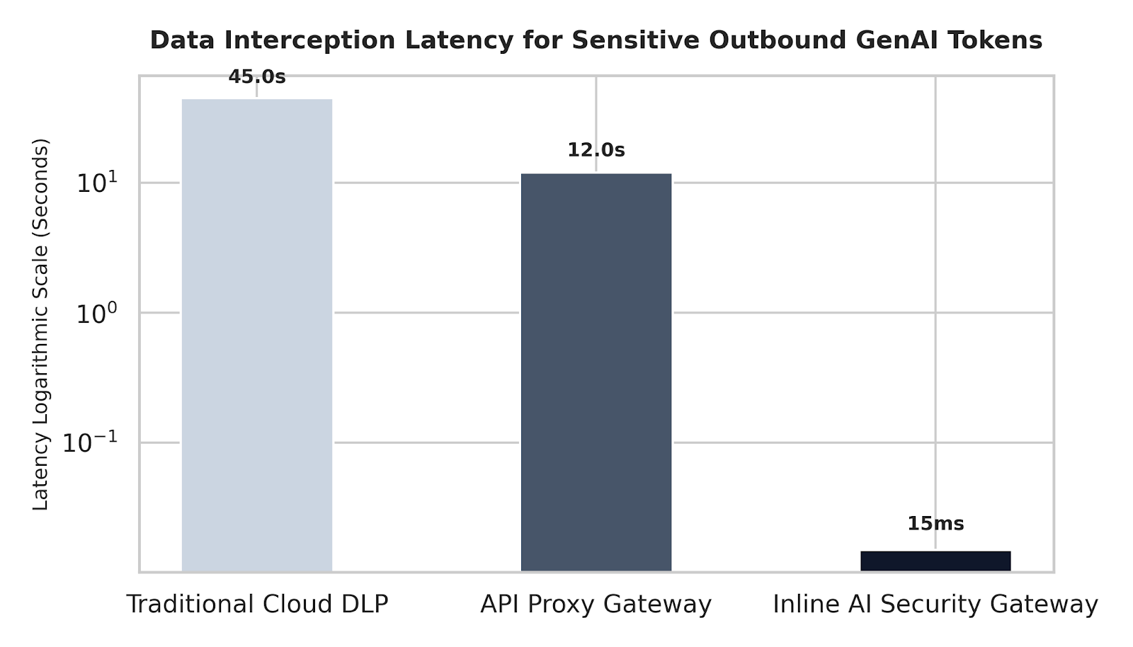
Manufacturing network deployment audits show that different filtering setups experience drastically different response times when evaluating and intercepting active token streams.
The visual matrix below maps intercept speeds across primary network deployment modes under intense outbound traffic loads:
Core Elements of a Shadow AI Prevention Strategy
A robust security framework built to counter shadow AI must integrate several closely linked capabilities:
-
Continuous Employee AI Usage Monitoring: Running non-intrusive network audits to track where data is going across all active internal endpoints.
-
Automated AI App Discovery Enterprise Systems: Creating a real-time, living inventory of every external LLM, browser extension, and model API utilized across the firm.
-
Granular Policy Enforcement Rules: Giving security teams the ability to block dangerous web platforms completely while allowing safe, view-only access to helpful tools.
-
Contextual Data Protection Guards: Examining the meaning of outgoing data requests to catch sensitive corporate secrets that standard text-matching rules miss.
Selecting an Intelligent Governance Architecture
When evaluating new visibility tools, risk teams must prioritize platforms that allow them to adopt technology safely rather than trying to block all AI traffic. Complete bans are rarely effective because they encourage workers to find clever ways around security controls to maintain their productivity.
Transitioning to adaptive platforms that combine shadow AI monitoring with automated shadow AI prevention controls allows companies to manage shadow AI risks effectively. This dual capability protects data while helping teams extract maximum value from corporate technology assets.
Conclusion
The spread of unmanaged shadow AI tools represents a significant data security threat that requires active, automated monitoring solutions. The ease of access to public LLMs means that old web-blocking rules are no longer sufficient to protect corporate data. As these tools continue to evolve, adopting specialized, behavior-focused discovery engines is absolutely necessary for eliminating data blind spots — allowing organizations to safely embrace AI productivity while keeping corporate assets fully protected.

Targeted Vertical Incubation: Strategic Alignment in Technical Software Venture Co-Investments

The Critical Technical SEO Audit Checklist for Enterprise SaaS Environments

Shadow AI Detection: Regaining Visibility Over Unsanctioned Enterprise Tooling

-

 Business Solutions2 years ago
Live Video Broadcasting with Bonded Transmission Technology
-

 Business Solutions1 year ago
The Future of Healthcare SMS and RCS Messaging
-

 Business Solutions2 years ago
2-Way Texting Solutions from Company Message Services
-

 Business Solutions2 years ago
Communication with Analog to Fiber Converters & RF Link Budgets
-

 DSRC Communication1 year ago
The Crossroads of Connectivity: DSRC vs. C-V2X Technologies in Automotive Communication
-
Electronics3 years ago
AI Modules and Smart Home Chips: Future of Home Automation
-

 Business Solutions2 years ago
Wholesale SMS Platforms with OTP Services
-

 Business Solutions1 year ago
Choosing the Right B2B Digital Marketing Agency: A Guide