


Software
Smart City Communications: The Network Infrastructure Behind Smarter, Safer Urban Environments
Smart cities are no longer a vision — they are an active deployment reality for municipalities, utility operators, and government agencies worldwide. But the promise of smarter traffic management, more efficient public services, lower energy consumption, and improved emergency response depends entirely on one foundational capability: reliable, scalable smart city communications infrastructure that connects thousands of sensors, cameras, and edge devices back to the platforms that analyze and act on their data.
This article examines the communications architecture that underlies smart city deployments, the specific connectivity challenges municipalities face, and how layered IoT and Ethernet networking solutions are enabling cities to move from isolated pilot programs to city-wide operational networks.
The Smart City Communications Stack: A Layered Architecture
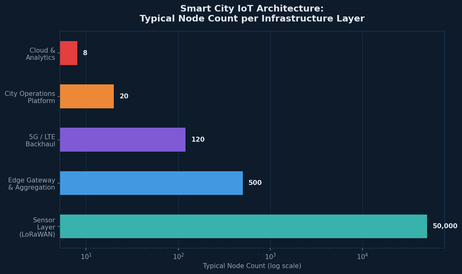
Effective smart city communications are not built on a single technology — they are built on a hierarchy of complementary connectivity layers, each optimized for a different class of device and use case:
- Sensor and device layer: Battery-operated environmental sensors, parking monitors, flood sensors, and utility meters communicate over LoRaWAN — a low-power, long-range protocol designed for small-payload IoT data across wide areas.
- Edge gateway and aggregation layer: LoRaWAN gateways and cellular IoT devices aggregate field data and forward it over higher-bandwidth backhaul to city network infrastructure.
- Access and backhaul layer: 5G, LTE, and Ethernet circuits carry aggregated IoT data, CCTV streams, and traffic management traffic from distributed edge points to city operations centers.
- Operations platform layer: City management platforms ingest, correlate, and act on data from hundreds of thousands of endpoints — generating alerts, automating responses, and providing dashboards for city operators.
The network infrastructure solutions required to support this stack must span diverse connectivity technologies, operate reliably in outdoor urban environments, and scale from pilot deployments to city-wide networks without architectural redesign.
LoRaWAN: The Connectivity Backbone for Smart City IoT Sensors
For the sensor layer — the thousands or tens of thousands of low-power devices that populate a smart city deployment — LoRaWAN has emerged as the dominant connectivity protocol. Its key characteristics make it uniquely suited to municipal IoT deployments:
- Range up to 10-15km in urban environments with line-of-sight conditions
- Multi-year battery life for sensor devices operating on small batteries or energy harvesting
- Unlicensed spectrum operation eliminating the need for cellular carrier agreements
- Scalable to millions of devices per network with appropriate gateway density
RAD’s SecFlow-1p and ETX-1p devices integrate LoRaWAN gateway functionality with business-class IP routing in a single ruggedized device — enabling cities to deploy LoRaWAN sensor connectivity and IP network infrastructure from a single platform. This integration reduces both deployment cost and operational complexity compared to architectures that require separate LoRaWAN and IP edge devices.
Remote IoT Data Monitoring: Turning Sensor Data into Operational Intelligence
Collecting sensor data is only the first step. The operational value of smart city infrastructure is realized through remote IoT data monitoring — the continuous analysis of sensor streams to detect events, identify trends, and trigger automated responses. For municipalities, this capability enables:
- Flood and environmental monitoring: River level sensors and rain gauges trigger early warning alerts hours before flood events reach urban areas.
- Smart street lighting: Occupancy sensors and light level monitors enable adaptive street lighting that reduces energy consumption by 30-60% compared to fixed schedules.
- Asset tracking and infrastructure monitoring: Vibration and tilt sensors on bridges, tunnels, and public infrastructure provide continuous structural health monitoring.
- Water utility management: Flow meters and pressure sensors detect leaks in real time, reducing non-revenue water losses and enabling proactive maintenance.
| Smart City Application | Connectivity Technology | RAD Device |
| Flood / Weather Sensors | LoRaWAN | SecFlow-1p / ETX-1p |
| Smart Street Lighting | LoRaWAN + Ethernet | SecFlow-1p |
| CCTV & Surveillance | Ethernet / 5G | ETX-2i series |
| Traffic Management | Ethernet + LTE | SecFlow-1v |
| Water Utility Meters | LoRaWAN | ETX-1p (LoRaWAN GW) |
First Responder and Public Safety Communications in Smart City Networks
Smart city communications infrastructure increasingly serves as the backbone for public safety and first responder networks. Police body cameras, emergency dispatch systems, and incident command communications all flow over the same urban network infrastructure that carries parking sensors and smart lighting — making the reliability and security of that infrastructure a public safety matter.
RAD’s SecFlow-1v — recognized with an IoT Security Excellence award — provides the integrated cybersecurity capabilities required when smart city networks carry safety-critical traffic. Its firewall, VPN, and access control features ensure that smart city IoT traffic is isolated from public safety communications, preventing interference and protecting against cyber threats.
Scaling Smart City Networks: From Pilot to City-Wide Deployment
Many smart city programs struggle with the transition from successful pilots to full-scale municipal deployments. The technical and operational challenges that are manageable at 50 devices become critical at 50,000. Key factors that determine scalability include:
- Zero-touch device provisioning: Manually configuring thousands of edge devices is operationally impossible; ZTP is essential for city-scale rollout.
- Centralized remote management: A unified NOC platform that manages all edge devices — regardless of connectivity type — is necessary for city-scale operations.
- Modular network architecture: Designs that allow new use cases and device types to be added without redesigning the underlying network infrastructure.
According to McKinsey’s Global Smart City Report, cities that invest in scalable, platform-based IoT infrastructure recover their technology investment significantly faster than those that deploy fragmented, use-case-specific systems — underlining the importance of architecture decisions made at the outset of smart city programs.
RAD’s Smart City Communications Portfolio
RAD’s approach to smart city IoT communications combines LoRaWAN gateway integration, ruggedized Ethernet access, and IoT security capabilities into a cohesive product portfolio purpose-built for municipal deployments. RAD devices are certified for outdoor and harsh environments, support remote management via standard network management protocols, and integrate with major IoT platform vendors through standard APIs.
With RAD as a network infrastructure partner, municipalities gain both the edge connectivity hardware and the integration expertise to build smart city networks that scale from initial deployment through full city-wide operation. For current RAD smart city deployment perspectives and technical articles, Tech PR Online regularly features RAD’s urban connectivity innovations.
Conclusion
Smart city communications are not a single technology — they are a carefully engineered ecosystem of complementary connectivity layers, purpose-built edge devices, and integrated management platforms. Cities that invest in the right foundational network infrastructure today — scalable, secure, and multi-technology — are building the platform for a generation of urban innovation. Those that treat connectivity as an afterthought risk finding their smart city ambitions constrained by the infrastructure choices made at the start.

At a Glance
- Drone imaging and drone inspections have emerged as two of the fastest-growing application segments in commercial UAV operations – each requiring different sensor capabilities, flight profiles, and data processing workflows.
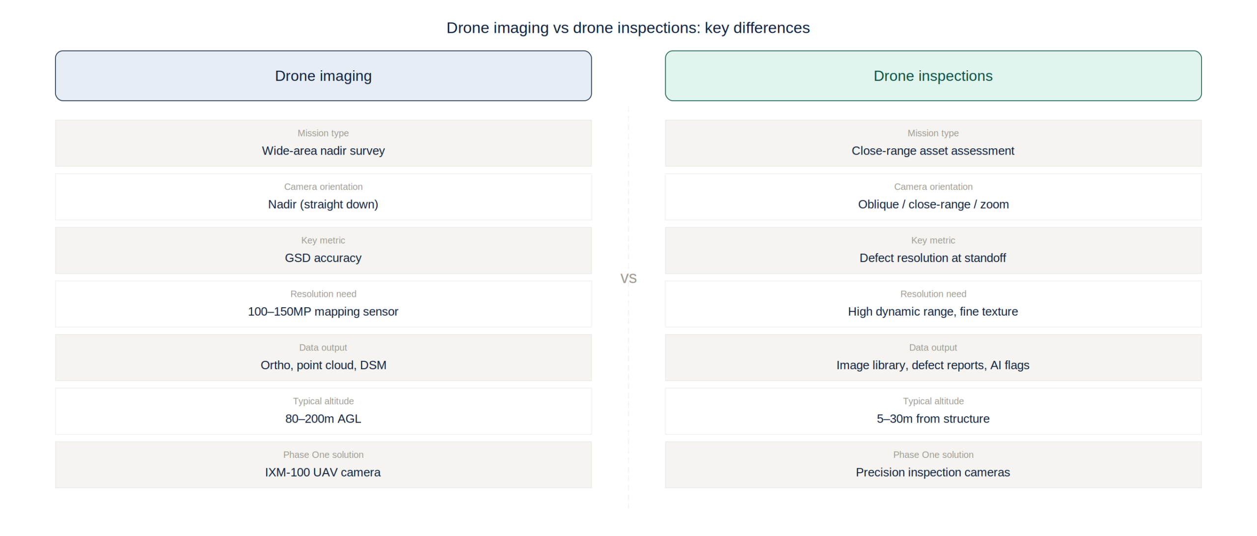
- The distinction between a drone imaging platform optimised for mapping and a drone inspection system optimised for close-range asset assessment is significant: camera resolution, lens choice, stabilisation, and lighting all differ substantially between the two use cases.
- Market demand for both applications is accelerating: infrastructure owners, energy operators, telecoms companies, and government agencies are all increasing their drone program budgets as ROI from drone-based data collection becomes well established.
- Phase One’s dual capability – high-resolution mapping cameras for drone imaging missions and precision inspection cameras for asset assessment — makes it the platform vendor of choice for operators who serve both markets.
Drones have become the workhorses of commercial geospatial data collection – but the phrase ‘drone operations’ covers a range of applications so diverse that grouping them under a single technology label obscures more than it reveals. Drone imaging for topographic mapping, corridor surveying, and 3D model generation requires fundamentally different hardware, software, and operational protocols than drone inspections of bridges, power lines, wind turbines, and oil and gas infrastructure. Understanding these differences is essential for operators, asset owners, and technology buyers selecting platforms and cameras for specific mission requirements.
Drone Imaging: Mapping, Surveying, and 3D Modelling
Drone imaging for geospatial applications – mapping terrain, producing orthomosaics, generating point clouds, and creating 3D digital twins – requires cameras optimised for nadir (downward-looking) capture with consistent overlap and a wide field of view. The key performance metrics are ground sample distance (GSD), radiometric calibration accuracy, and geometric stability under variable lighting conditions.
Phase One’s IXM-100 and related UAV camera solutions are designed specifically for drone imaging missions requiring sub-5cm GSD and radiometrically calibrated imagery suitable for quantitative analysis. The 100-megapixel sensor captures substantially more detail per frame than the 20-45MP sensors used in consumer and prosumer drone cameras – enabling higher flight altitude for the same GSD, reducing flight time and increasing mission efficiency without sacrificing the resolution that professional deliverables demand.
The commercial drone imaging market includes well-established players such as DJI’s mapping-oriented platforms, Sony’s RX1R II-based solutions, and integrated systems from Micasense and Parrot. Phase One occupies the professional-grade tier of this market, where accuracy requirements exceed consumer drone capabilities and clients have zero tolerance for survey rework caused by inadequate image resolution or unstable sensor geometry.
Drone Inspections: Close-Range Asset Assessment
Drone inspections address a fundamentally different imaging challenge from mapping surveys. Rather than capturing consistent nadir imagery over wide areas, inspection missions require close-range photography of specific asset features – cracks in concrete structures, corrosion on steel components, damage on rotor blades, insulator defects on power lines – where the ability to resolve fine detail at challenging angles and lighting conditions determines whether defects can be identified and characterised accurately.
The sensor requirements for inspection differ accordingly: higher dynamic range to handle the contrast between bright sky and shadowed structure surfaces; zoom capability or interchangeable telephoto lenses for close-up capture from safe standoff distances; and either mechanical stabilisation or gyro-stabilised mounting to maintain image sharpness during proximity flight. For thermal inspection applications – increasingly used for electrical system monitoring, building envelope assessment, and solar panel inspection – thermal sensors with high spatial resolution and accurate temperature measurement are required alongside or instead of RGB cameras.
Leading drone inspection platforms include purpose-built systems from Flyability (confined space inspection), Skydio (autonomous close-range inspection with obstacle avoidance), and DJI’s Dock-based enterprise inspection solutions. Phase One’s inspection camera solutions integrate with these platforms, providing the high-resolution imaging capability that professional inspection workflows demand – particularly for applications where defect documentation must withstand legal and regulatory scrutiny.
Key Differences: Camera Requirements by Application
The camera requirements for drone imaging versus drone inspections diverge significantly across five dimensions. Resolution: drone imaging benefits from maximum pixel count for GSD efficiency; inspection benefits from targeted high resolution at close range with the ability to capture fine texture detail in variable lighting. Lens: mapping uses wide-angle prime lenses for consistent geometric coverage; inspection uses longer focal lengths for standoff distance and portrait-orientation capture of vertical structures.
Processing: mapping data is processed in photogrammetry pipelines (Pix4D, Agisoft, iX Suite) to generate 3D models and orthomosaics; inspection imagery is reviewed frame-by-frame or processed through AI defect detection systems trained on specific asset types. Regulatory: mapping flights typically operate at altitude with automatic collision avoidance; inspection flights often operate at low altitude around structures, requiring specific waiver approvals and manual pilot control. Data volume: mapping missions generate tens of thousands of overlapping images processed as a batch; inspection missions generate targeted image sets structured around specific asset elements and numbered reference points.
Phase One’s portfolio addresses both requirements: the IXM-100 for drone imaging missions requiring maximum GSD efficiency and radiometric accuracy, and precision inspection camera solutions for close-range asset documentation requiring high dynamic range and fine detail resolution.
The ROI Case for Professional Drone Cameras
The business case for investing in professional-grade drone cameras – rather than relying on cameras integrated into consumer drone platforms – is most compelling for operators who serve multiple mission types, maintain repeat client relationships, and face accuracy requirements that consumer cameras cannot reliably meet.
For drone imaging, the accuracy premium of a Phase One IXM-100 system versus a DJI Phantom 4 RTK translates directly into deliverable quality: orthomosaics with sharper feature resolution, point clouds with higher density per flight hour, and digital elevation models with better vertical accuracy. For professional mapping clients – infrastructure owners, government agencies, and engineering firms – these quality differences justify the price premium through reduced survey repeat rates, fewer ground control requirements, and longer useful life of acquired datasets.
For drone inspections, the primary ROI driver is defect detection reliability. A missed defect on a wind turbine blade, a bridge bearing, or a high-voltage insulator can cost orders of magnitude more than the inspection program itself. Professional inspection cameras with sufficient resolution and dynamic range to document marginal defects – those at the limit of detectability – provide an insurance value that dwarfs their acquisition cost when measured against the cost of structural failure or unplanned maintenance.
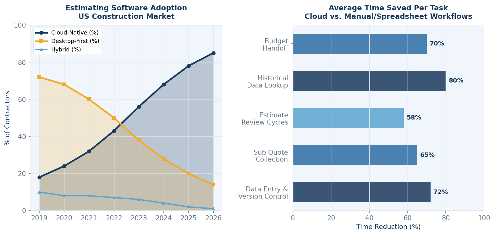
If your estimating team is still piecing together bids in Excel, you’re working harder than you need to be. Spreadsheet-based estimating isn’t wrong, exactly – plenty of experienced estimators can build detailed cost models in Excel – but it doesn’t scale well, creates version control headaches, and makes collaboration across distributed teams unnecessarily difficult.
Cloud-based construction estimating software has addressed most of those pain points. The platforms available to US contractors today are more capable and more affordable than they were five years ago. The harder part is picking the right one.
This guide covers the top cloud estimating software options for construction teams in the US, with a focus on what each platform is actually good at and which types of contractors get the most value from each.
Why Cloud Estimating Matters More Than It Did
The practical case for cloud estimating software comes down to three things: collaboration, accuracy, and data retention.
Collaboration is the obvious one. When your estimates live in the cloud, project managers, estimators, and procurement teams can all work from the same data set without emailing files back and forth. The version control problem largely disappears.
Accuracy improves because cloud platforms can pull from historical cost data, apply pricing models based on past projects, and flag outliers automatically. Manual entry into spreadsheets doesn’t offer any of that.
Data retention is the part most contractors underestimate. Every estimate your team produces is an asset. Cloud platforms build that data into a searchable, analyzable library that gets more valuable the longer you use it. That kind of institutional knowledge is nearly impossible to replicate in a folder of Excel files.
Top Cloud Estimating Software for US Contractors: 2026 Comparison
| Platform | Cloud-Native | Bid Integration | Analytics | Best Fit |
| ConWize | Yes | Full | Predictive + KPIs | GCs & Subs |
| Sage Estimating | Partial | Limited | Basic | Enterprise |
| Trimble WinEst | Hybrid | Moderate | Moderate | Mid-large GCs |
| Stack CT | Yes | Partial | Basic | Estimating-first |
| Clear Estimates | Yes | Minimal | None | Residential |
ConWize: Cloud Estimating Built Around the Bidding Process
ConWize is a fully cloud-based construction estimating and bidding platform, and it’s the option that most directly integrates cost estimating with the sub-bidding workflow. For teams where estimating and bid management happen in parallel – which is most commercial GCs – that integration matters a lot.
The platform’s cost estimating software includes advanced cost estimation tools, price analysis, indirect cost management, profit loading calculations, and a KPI dashboard that tracks performance across projects. The predictive analytics feature is particularly valuable for teams that have built up a history on the platform – it draws on past project data to flag unusual quotes and help estimators benchmark their numbers.
What separates ConWize from most alternatives is the connection between estimating and procurement. The cost model doesn’t sit isolated in an estimating module; it connects directly to the sub-bidding process, so the numbers your estimators work with are informed by actual quotes from the market. That feedback loop significantly improves accuracy over time.
For US contractors running multiple projects simultaneously, the multi-project dashboard gives a real-time view of where every estimate stands, which bids are outstanding, and how different project numbers compare against each other.
Sage Estimating: Established but Desktop-Anchored
Sage Estimating has been around for decades and is trusted by large US contractors, particularly in the commercial and heavy civil sectors. Its cost database integration and assembly-based estimating are strong. The platform’s cloud transition has been gradual, and some of its most powerful features still work best as desktop-installed software. For teams that need a pure cloud workflow with real-time collaboration, that’s a meaningful limitation.
Trimble WinEst: Good Depth, Steep Onboarding
Trimble’s WinEst is a capable mid-to-large contractor platform with solid estimating depth. The learning curve is steeper than most, and the pricing reflects that it’s positioned for larger organizations. The hybrid cloud-desktop architecture is more capable than some older platforms but still falls short of fully cloud-native tools when it comes to collaboration features.
Stack CT and Clear Estimates
Stack Construction Technologies does takeoff well. If your team’s primary bottleneck is measuring quantities from plans, Stack is worth serious consideration. Its estimating module covers the basics but doesn’t have the bid analytics depth or the preconstruction workflow integration of more specialized platforms. Clear Estimates is a lightweight tool designed for residential remodelers – easy to learn, but not built for complex commercial estimating or multi-trade bid management.
What to Look for When Choosing
- True cloud-native architecture – not desktop software with a cloud sync feature
- Historical data and analytics – the platform should get smarter the longer you use it
- Integration between estimating and bidding – cost models should reflect actual market quotes
- Multi-project visibility – dashboards that give you a cross-project view without switching between files
- Collaboration features – real-time access for estimators, PMs, and procurement teams
Industry research from Engineering News-Record (ENR) consistently highlights that firms adopting cloud-based estimating and procurement platforms are winning a higher percentage of competitive bids and maintaining tighter budget control through execution. The shift is already well underway in the US market.
Wrapping Up
For US construction teams looking to improve estimate accuracy, reduce rework, and build a data library that actually gets more useful over time, ConWize is the cloud estimating platform that most effectively connects the estimating workflow with the broader bidding and procurement process. The alternatives have their merits, but most address pieces of the problem. ConWize treats it as a whole.
The global 5G rollout has moved well past the early-adopter phase. In 2025, mobile operators, enterprises, and critical infrastructure providers are actively deploying 5G networks — and the range of 5G use cases enabled by this technology continues to expand. From enhanced mobile broadband to mission-critical machine communications, 5G is fundamentally reshaping what is possible at the network edge.
Yet the success of 5G deployments depends heavily on underlying transport infrastructure. Cell site connectivity — fronthaul, midhaul, and backhaul — must be engineered to handle the strict latency, synchronization, and bandwidth requirements that 5G imposes. This article explores the most important 5G use cases driving network evolution in 2025 and the transport infrastructure innovations enabling them.
Understanding the 5G Use Case Landscape
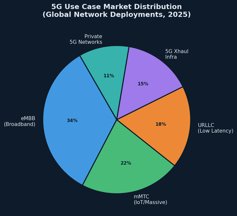
The 3GPP standards body defines three primary 5G service categories, each demanding different network characteristics:
- eMBB (Enhanced Mobile Broadband): High-bandwidth applications including 4K/8K video, augmented reality, and fixed wireless access. Demands high throughput but tolerates moderate latency.
- mMTC (Massive Machine-Type Communications): Large-scale IoT deployments — smart city sensors, utility meters, logistics tracking. Requires broad coverage and energy efficiency over raw speed.
- URLLC (Ultra-Reliable Low-Latency Communications): Mission-critical applications including autonomous vehicles, industrial automation, and remote surgery. Demands sub-millisecond latency and extremely high reliability.
Each category places distinct requirements on network transport — and the infrastructure choices made at the cell site determine whether these SLAs can actually be met.
5G Xhaul: The Transport Architecture Enabling Every Use Case
5G xhaul is the collective term for the fronthaul, midhaul, and backhaul transport segments that connect 5G radio units (RUs), distributed units (DUs), and centralized units (CUs) to the core network. As 5G architectures disaggregate radio functions, xhaul transport becomes more complex — and more consequential.
Fronthaul — connecting RU to DU — carries raw radio samples and demands the strictest timing: sub-100 nanosecond synchronization accuracy aligned with IEEE 1588 Precision Time Protocol (PTP). Midhaul connects DU to CU, typically requiring microsecond-level latency. Backhaul, connecting CU to the core, carries aggregated user traffic and must support high bandwidth with deterministic behavior.
RAD’s all-in-one 5G xhaul cell site gateway simplifies this architecture by integrating fronthaul, midhaul, and backhaul transport into a single, compact device. This consolidation reduces cell site footprint, simplifies operations, and provides a unified point of management for all xhaul transport segments — a significant advantage for operators managing thousands of 5G sites.
Top 5G Use Cases Reshaping Networks in 2025
| 5G Use Case | Key Network Requirement | Primary Sector |
| 5G Fronthaul/Midhaul | Sub-100ns sync, low latency | Telecoms / CSP |
| Private 5G Networks | Network slicing, isolation | Industry / Manufacturing |
| Smart City IoT | mMTC, LoRaWAN integration | Government / Municipal |
| Fixed Wireless Access | High throughput eMBB | Residential / Enterprise |
| Critical Infrastructure | URLLC, high availability | Utilities / Transport |
Private 5G Networks: The Enterprise 5G Use Case Gaining Momentum
Private 5G networks — where enterprises deploy their own licensed or shared spectrum 5G infrastructure on-premises — are among the fastest-growing segments of the 5G use case landscape. Manufacturing plants, logistics hubs, ports, and mining operations are deploying private 5G to enable mobile automation, real-time quality inspection, and autonomous vehicle coordination.
The appeal is clear: private 5G offers the coverage, latency, and reliability of 5G with the security and control of a private network — without depending on shared public 5G capacity. For operators of critical assets, this control is invaluable.
RAD’s 5G cell site gateway solutions are designed to support both public and private 5G deployments, providing the synchronization accuracy and transport flexibility required for disaggregated RAN architectures used in private 5G environments.
5G and Smart City Communications: Connecting Urban Infrastructure
Smart city applications represent one of the most visible and socially impactful 5G use cases in deployment today. Traffic management systems, environmental monitoring networks, connected streetlights, and public safety communications are all candidates for 5G-connected infrastructure.
The convergence of 5G with LoRaWAN — which handles low-power, long-range sensor connectivity — creates a layered urban connectivity architecture. 5G handles bandwidth-intensive and latency-sensitive applications, while LoRaWAN aggregates data from battery-powered sensors across the city. RAD’s ETX-1p combines business routing with LoRaWAN gateway functionality, making it a practical building block for smart city deployments that span both connectivity layers.
Network Synchronization: The Hidden Enabler of 5G Use Cases
Beneath every 5G use case lies a synchronization requirement that is often underestimated until it causes problems. Fronthaul timing accuracy, inter-site coordination for interference management, and network slicing all depend on a timing fabric that extends from the core to every cell site.
IEEE 1588v2 Precision Time Protocol (PTP) and SyncE are the standards-based mechanisms used to distribute timing across 5G transport networks. RAD’s solutions support both, with hardware timestamping accuracy that meets the strictest 5G fronthaul timing requirements. This capability is not optional for URLLC or massive MIMO deployments — it is fundamental.
RAD’s 5G Transport Portfolio: Built for Every Xhaul Segment
RAD has positioned its network edge portfolio to address the full range of 5G transport requirements — from cell site gateway consolidation to Ethernet demarcation for 5G business services. The company’s all-in-one 5G xhaul solution provides a cost-effective approach to multi-segment transport, while the ETX-2i series delivers MEF-certified demarcation for 5G-delivered enterprise services.
With deep expertise in timing, synchronization, and carrier-grade Ethernet — and a global deployment footprint spanning 150+ countries — RAD brings both the technology and the operational experience to help carriers execute successful 5G infrastructure builds at scale.
Conclusion
The 5G use case landscape in 2025 is broad, diverse, and accelerating. From smart cities and private industrial networks to mission-critical URLLC applications, the value of 5G depends entirely on the quality of the transport infrastructure beneath it. Network operators who invest in purpose-built xhaul solutions today are laying the foundation for a decade of 5G service innovation — and the competitive advantages that come with it.

Targeted Vertical Incubation: Strategic Alignment in Technical Software Venture Co-Investments

The Critical Technical SEO Audit Checklist for Enterprise SaaS Environments

Shadow AI Detection: Regaining Visibility Over Unsanctioned Enterprise Tooling

-

 Business Solutions2 years ago
Live Video Broadcasting with Bonded Transmission Technology
-

 Business Solutions1 year ago
The Future of Healthcare SMS and RCS Messaging
-
 Business Solutions2 years ago
2-Way Texting Solutions from Company Message Services
-

 Business Solutions2 years ago
Communication with Analog to Fiber Converters & RF Link Budgets
-

 DSRC Communication1 year ago
The Crossroads of Connectivity: DSRC vs. C-V2X Technologies in Automotive Communication
-
Electronics3 years ago
AI Modules and Smart Home Chips: Future of Home Automation
-

 Business Solutions2 years ago
Wholesale SMS Platforms with OTP Services
-

 Business Solutions1 year ago
Choosing the Right B2B Digital Marketing Agency: A Guide