


Tech
PCB Design for Medical Devices: What Actually Has to Go Right

| Key Takeaways
• Medical device PCB design has to satisfy miniaturization, biocompatibility, long-term reliability, and, for imaging-adjacent devices, MRI/CT compatibility all at once. • Devices used near MRI or CT equipment can only use paramagnetic metals, since magnetic materials can distort imaging or react to the machine’s field. • FDA design controls under 21 CFR 820.30 require documented design input, output, verification, validation, and independent design review at each development stage. • The global implantable medical devices market is projected to grow from about $110.9 billion in 2026 to $179.4 billion by 2034, an independent analyst estimate. |
What makes PCB design for medical devices different from standard electronics?
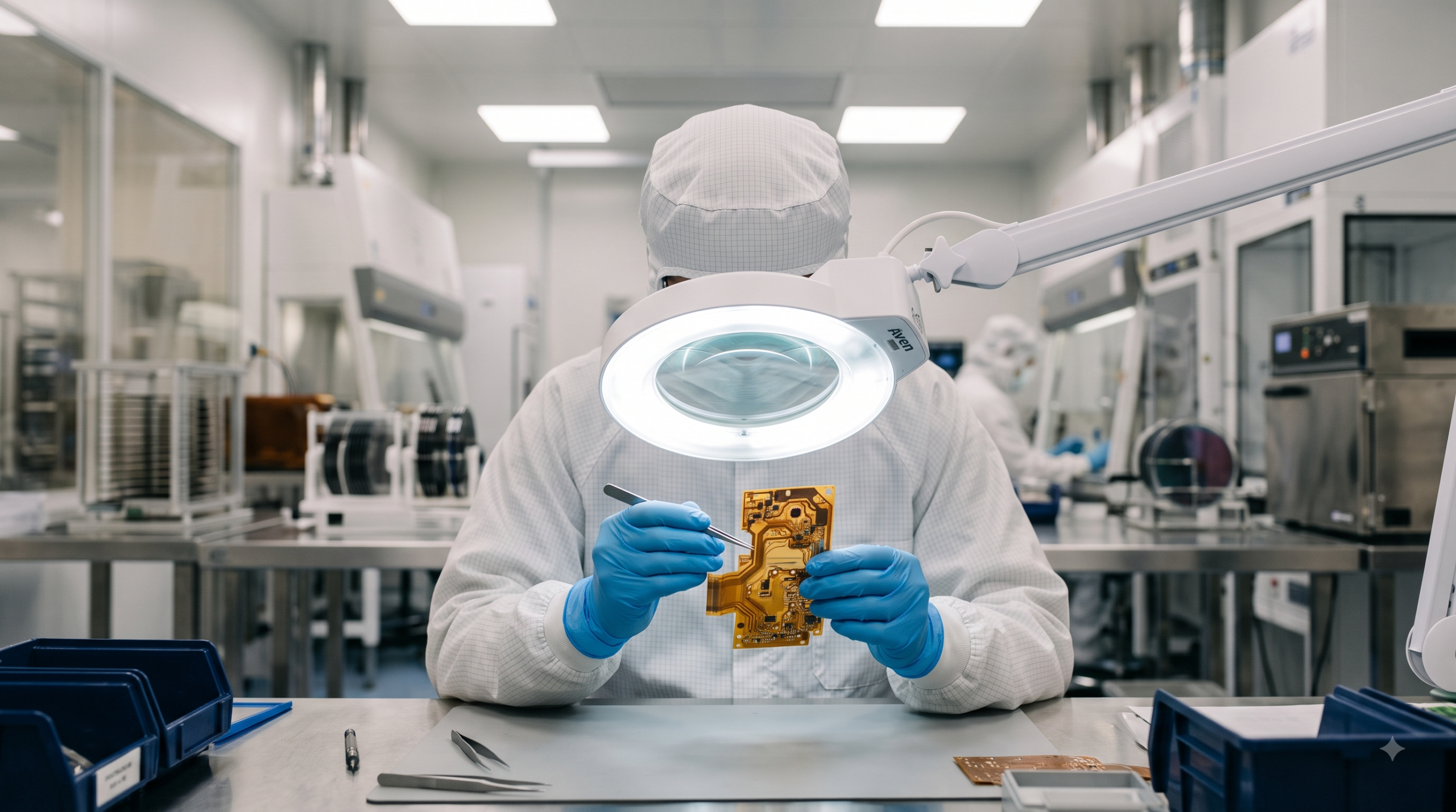
Medical device PCB design differs from standard electronics primarily in four areas: miniaturization, biocompatibility, long-term reliability, and, for certain devices, imaging compatibility. A board destined for an implant, a wearable monitor, or diagnostic imaging equipment has to satisfy all four simultaneously, not just meet a single performance spec, because a failure in any one of them can affect patient safety rather than just product quality. the medical electronics PCB requirements outlined here breaks these four parameters down in more detail across implantable, diagnostic, wearable, and therapeutic device categories.
Why does miniaturization matter so much in medical PCB design?
Miniaturization matters because many medical applications — pacemakers, neurostimulators, cochlear implants, insulin pumps — have almost no room to spare, so the board has to shrink without giving up reliability. Achieving that typically means fine-line copper traces, ultra-flex materials, rigid-flex stack-ups that fold into the available space, and embedded cavities that let passive components sit inside the board rather than on its surface, all of which add manufacturing complexity compared with a conventional rigid board. Wearable monitors face a related but slightly different version of this pressure: rather than fitting inside a surgical implant site, they need a form factor thin and flexible enough to sit comfortably against skin for extended periods, which pushes many of the same rigid-flex and fine-line techniques into a lower-cost, higher-volume product category.
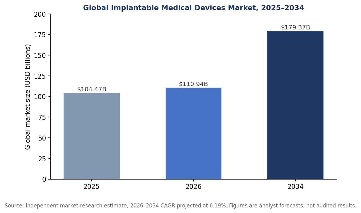
The global implantable medical devices market is projected to grow from roughly $110.9 billion in 2026 to $179.4 billion by 2034, an independent analyst estimate reflecting rising demand for implantable and minimally invasive devices.
What does biocompatibility actually require from a PCB’s materials?
Biocompatibility requires that any material in contact with tissue, or close enough to affect it, be non-toxic and non-reactive with living biological systems — a requirement that rules out certain standard PCB finishes and adhesives outright for implantable use. For devices used inside or near MRI or CT equipment, there’s a second material constraint on top of biocompatibility: only paramagnetic metals are acceptable, since any process, coating, plating, or component with magnetic characteristics can distort imaging results or physically react to the machine’s magnetic field.
How do FDA design controls shape the medical PCB design process?
FDA design controls under 21 CFR 820.30 require manufacturers to formally document design input, design output, verification, and validation at each stage of development, with a documented design review — including at least one independent reviewer — before moving forward. The practical effect on a PCB program is that layout, material, and component decisions need to be traceable back to a documented requirement, and any change has to go through the same verification and validation loop rather than being made informally on the bench. FDA design control guidance for medical device manufacturers notes that catching design errors early, before they reach production, is consistently cheaper than correcting them later — one of the main reasons this process exists in the first place.
How do miniaturization and reliability requirements sometimes pull in opposite directions?
Shrinking a board’s footprint and keeping it reliable over years of use can genuinely conflict: finer traces and thinner dielectrics save space but leave less margin for manufacturing variation, and embedded components are harder to inspect after assembly than parts mounted on the surface. Programs working through that tension typically lean on the same design-verification discipline required elsewhere in medical device development — testing miniaturized prototypes against the same reliability bar as a larger, easier-to-inspect board, rather than assuming a smaller design is automatically an equivalent one.
What role does ISO 13485 play alongside FDA requirements?
ISO 13485 is a quality management system standard specific to medical devices, covering risk management, design control, documentation, and traceability across the manufacturing process rather than any single design decision. background on the ISO 13485 quality management standard notes that certification under this standard is typically the first step toward meeting European regulatory requirements and obtaining the CE mark needed to sell a device in the EU, which is why manufacturers pursuing both US and European markets tend to build their quality systems around it from the start. this overview of PCBs as the core component in medical equipment covers how that quality-system discipline connects back to the physical board itself.
What kind of testing do medical PCBs typically go through before they’re deployed?
Manufacturers serving demanding medical-device customers commonly maintain several distinct inspection capabilities rather than relying on a single pass/fail test: chemical analysis labs to verify material composition and contamination, metallographic cross-sectioning to physically examine plating thickness and via structure, and highly accelerated stress testing (HATS) to force latent defects to the surface faster than they’d appear in normal use. Running a board through all three isn’t about redundancy for its own sake — chemical, structural, and stress-based failure modes are genuinely different, and a board that passes one type of inspection can still fail another, which is exactly the kind of gap a documented FDA design-verification process is meant to catch before it reaches a patient.
What has driven the recent push toward smaller medical electronics?
The push toward smaller medical electronics has been driven largely by demand for minimally invasive procedures and wearable, continuous-monitoring devices, both of which require electronics that fit into far less space than earlier generations of equipment. coverage of the miniaturization trend in medical device design traces how that shift has changed expectations for trace width, layer count, and component density on medical boards. A separate, independently published look at how a design becomes a finished board — the fabrication process from raw copper to a finished board — is useful background for understanding why process discipline earlier in fabrication affects reliability outcomes later in a medical device’s life.
How does long-term reliability differ for an implanted device versus a hospital-based one?
An implanted device generally has to meet a much higher reliability bar than hospital-based diagnostic or therapeutic equipment simply because it can’t be swapped out or repaired without surgery, so a board defect that would be a service call for a bedside monitor becomes a much more serious event for something like a pacemaker or neurostimulator. That difference shows up in practice as tighter component derating, more conservative trace and via design margins, and often additional burn-in or environmental screening before a board is accepted for an implantable program, on top of the reliability and repeatability requirements that apply across medical electronics generally.
Frequently Asked Questions
Why can’t standard PCB materials be used in implantable medical devices?
Standard PCB materials and finishes aren’t screened for biocompatibility, meaning they haven’t been confirmed as non-toxic and non-reactive with living tissue, which implantable applications specifically require.
Does every medical device need to follow FDA design controls?
Design controls under 21 CFR 820.30 apply to all Class II and Class III devices and to specific Class I devices, including those that include software, so most medical electronics fall under the requirement.
What is different about a PCB meant to be used near an MRI machine?
It can only use paramagnetic metals in its materials, plating, and components, since anything with magnetic characteristics can distort the MRI’s imaging field or physically interact with it.
Is ISO 13485 certification mandatory for medical device manufacturers?
It’s a voluntary standard rather than a legal mandate in most jurisdictions, but it’s typically the practical first step toward meeting European CE-marking requirements and is widely expected by medical device customers regardless.


Software
The AI Isn’t Wrong About Your Company. Your Sources Are | Interview with Aia Laser
An interview with Aia Laser, founder of AlignTo AI.


Most companies now check what ChatGPT and Gemini say about them. Far fewer ask where the answer came from. The uncomfortable finding, for those who trace it, is that it usually came from them.
Ask an AI assistant to describe a company and it will answer with confidence: what the company makes, where it is based, who it competes with. For a growing number of brands, that answer is wrong in ways that cost real deals. A manufacturer is placed in the wrong country. A product that was discontinued three years ago is presented as the flagship. A company that merged, rebranded or moved upmarket is described as the company it used to be.
The standard response is to treat it as a content problem: publish more, add structured data, chase citations. Practitioners who have traced AI answers back to their origins say the error sits upstream of any single page.
“An AI engine is not inventing a story about your company,” says Aia Laser, founder of AlignTo AI, a Tel Aviv startup that helps brands take control of how and why AI systems represent them. “It is assembling one from three inputs: your own site, what third parties say about you, and what it has already learned from both. When those three disagree, the model averages them. Most brands have never checked whether they agree.”
Tracing the answer to its source
Laser’s claim rests on an audit of an industrial manufacturer, one of AlignTo AI’s first clients. Her team captured hundreds of AI answers about the brand across several engines and traced every claim in them to one of three places: the company’s own site, a third-party page, or no page at all.
The company’s site stated its headquarters and manufacturing locations correctly, but in a handful of places and not always where a machine would read them. Distributor listings and directory pages, written years earlier, described it as a US or European manufacturer. And in ChatGPT’s answers, the brand was named correctly in 88 percent of cases without any cited page carrying the information: the model had already learned the company from the whole corpus, and the corpus did not agree with itself.
“Your site is the one input you fully control, and it is upstream of everything else,” Laser says. “Third parties copy it, and the models learn from both. If your site says the right thing once, quietly, and twenty distributor pages say something else, the model will not side with you. It will side with the majority.”
“People hear that and conclude the site does not matter,” Laser says. “It is the opposite. The site is where the correct version has to live, stated clearly and in a form AI can read, because everything else is copied from it or compared against it. The mistake is thinking the site is where the work ends.”
The practical consequence is a familiar story in marketing departments this year. A team spends a quarter rewriting product pages, the dashboard shows citations climbing, and the AI assistant still tells prospects the company is headquartered in the wrong country, because the pages the engines trust most were never the company’s own.
The identity the machines already hold
Laser says the problem begins one step earlier than most people look. “Before a model decides what your company does, it has to decide which company you are. That step is called entity disambiguation, and nobody in marketing is watching it. If your name is common, or shared with a competitor, or also an ordinary word, the model may merge you with someone else’s facts, or split you into two half-entities that each carry part of your story. Everything it says afterward is built on that decision.”
The decision is not hidden, she argues, and that is the part the industry misses. “Google’s Knowledge Graph is a database with an API. Wikidata is open. You can query them for your own entity and see exactly what the machines hold: what name and type they have for you, the one-line description they attach, which aliases they recognize, what identifier they assigned, and how confident the match is. That is real knowledge-graph probing, and it takes minutes. I have never had a company do it before we did it for them.”
What comes back is frequently a shock. “We have seen companies that exist in the graph as the wrong type, or under a name they stopped using years ago, or not at all. When the record is missing or wrong, every engine that leans on it is guessing, and it will guess from whatever third-party page it finds. So when an AI answer has no cited page behind it, the first question is not what the site says. It is what the identity record says.”
Who the memory hurts
A startup founded last year has little to fear from this. There is not much for a model to remember. The companies most exposed are the ones with the longest histories and the most to lose from being described as their former selves.
Post-merger companies are the clearest case. The acquired brand still exists in years of press coverage, directory listings and old partner pages, and the model has absorbed all of it. Long-established firms carry a legacy perception that may be a decade out of date. International companies find that each market has told a slightly different story about them, and the model has averaged the stories together. Any company that repositioned, dropped a product line or moved into a new category is, in the model’s memory, still where it started.
“The companies that come to us are not companies with bad content,” Laser says. “They are companies with a past. The model is faithfully describing a version of them that is still live in a hundred places they do not control, and usually in a few places they do. Nobody ever went back and reconciled the story.”
The damage is quiet. Nobody sees the deal that was never opened because a buyer asked an assistant for a shortlist and the company appeared under the wrong description, or did not appear at all.
Three causes, one diagnosis
The deeper problem, Laser argues, is that an AI misrepresentation can have three different causes, and each demands a different response. The industry mostly treats them as one.
| Cause | What it looks like | What actually fixes it |
| Owned-source gap | The brand’s own site never states the fact, states it inconsistently, or states it where AI cannot read it | Content and structure changes on the site |
| Third-party gap | Distributors, directories, publishers and partner pages carry the old or wrong story | Outreach and correction of the sources AI reads, prioritized by which ones engines actually cite |
| Model memory | The engine states the error with no page to support it | Correcting the identity record in the knowledge graphs, and keeping the site and corpus consistent with it over time; a single page change will not reach it |
“Attribution is the whole game,” she says. “If you cannot say which bucket a mistake sits in, you will spend the content budget on an error that content cannot touch, and ignore a distributor page that is quietly teaching every engine the wrong headquarters.”
Monitoring tools, in her view, are good at the first half of the job. They show what the engines are saying. What they rarely do is explain why, because explaining why requires a confirmed record of what is actually true about the company, and most companies have never written one down.
Showing a brand what AI knows about it
AlignTo AI was built to answer the question most monitoring tools leave open: not only what the engines say about a brand, but where each claim came from and why. The startup shows companies what AI currently knows about them, traces every misrepresentation back to its root source, whether on the brand’s own site, on a third-party page, or in the model’s identity record, and gives the company a way to decide and control how it is represented from there.
Aia Laser, who also founded the Tel Aviv B2B tech digital marketing agency (Inter-Dev), spent over a decade in leading SEO strategies for renowned Israel’s tech companies, before AI answers became a channel, frames it in plainer terms. “Would you let a new salesperson go out and talk about your brand without handing them the updated, correct data first? That is what every company is doing with AI right now. The engines are the salespeople. They are out there describing you to buyers all day, and nobody at the company has checked what they were trained on or told them what changed.”
The argument is that representation in AI is a governance problem, not a content problem.
“Brands have been outsourcing their own definition to whoever wrote about them last,” she adds. “AI just made the cost of that visible.”
What to do before the next audit
Aia Laser’s advice to companies that suspect the model has them wrong is to stop optimizing and start diagnosing.
- Capture answers with their citations, then trace every claim: is it on your site, on a third-party page, or on neither? That tells you where the model learned it.
- Write down what is true. One confirmed record of the company’s facts, agreed internally, is the baseline every audit needs and almost no company has.
- Check your own site against that record first. Every fact should be stated, consistent across pages, and readable by a machine.
- Sort every remaining error by cause before spending on any of them, and treat a change that shipped and moved nothing as information about where the error really lives.
“Everyone is asking how to get the AI to notice them,” she says.
“The harder question is what the AI already thinks it knows, and whether anyone at the company has ever decided what the answer should be.”

| Key Takeaways
• A delay line holds back an RF signal for a precise time and is used for radar and altimeter testing, signal-path alignment, phased-array beamforming and signal processing. • The four main delay line families are coaxial cable, acoustic (SAW and BAW), digital (ADC, memory and DAC) and fiber optic. • Coax and fiber add a similar delay of roughly 4 to 5 ns per meter, but single-mode fiber loses well under 1 dB per kilometer regardless of RF frequency, while coax loss rises with length and frequency. • Emulating a radar target at 10 km needs about 66 microseconds of round-trip delay, or roughly 13.6 km of single-mode fiber. |
What is a delay line?
A delay line is a component that holds back an RF or microwave signal for a precise, known amount of time and then releases it otherwise unchanged. Delay lines are used to emulate distance in radar and altimeter testing, to align the timing of parallel signal paths, to build true-time-delay beamformers for phased arrays and to provide short-term signal memory in correlators and receivers.
In radar work the delay always represents a round trip, which makes the numbers grow quickly. A SPIE conference paper comparing microwave analog delay line technologies points out that emulating a target only 50 m away already calls for 333.33 ns of delay, because the signal has to travel out and back. For readers who want the underlying vocabulary first, a broader primer on delay lines covers the terms used throughout this comparison.
What types of delay line are available?
There are four main families of RF delay line: coaxial cable, acoustic (surface or bulk acoustic wave), digital, and fiber optic. Each creates delay in a physically different way, and that physical mechanism determines its loss, bandwidth, size and flexibility.
| Technology | How the delay is created | Main strengths | Main limitations |
| Coaxial cable | The RF signal travels through a coiled length of coax, often semi-rigid | Simple, passive, no signal conversion | Bulky at long delays; loss rises with length and frequency |
| Acoustic (SAW / BAW) | RF is converted into an acoustic wave in a piezoelectric material, which travels far slower than an electromagnetic wave | Very compact for a given delay | High insertion loss, reported above 30 dB; SAW limited to roughly 2.5 GHz |
| Digital | The signal is sampled by an ADC, held in memory and regenerated by a DAC | Delay is programmable and can be combined with synthetic Doppler or modulation | Bandwidth and spurious performance set by the converters; adds latency of its own |
| Fiber optic (ODL) | RF is modulated onto light and delayed by a chosen length of single-mode fiber | Low loss that does not change with RF frequency; delays from nanoseconds to milliseconds | Requires optical conversion, which adds noise; each delay value needs its own fiber length or a switch path |
How do coaxial delay lines compare with fiber optic delay lines?
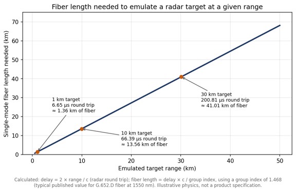
Coax and fiber produce a similar delay per meter, around 4 to 5 nanoseconds depending on the cable dielectric, but fiber achieves it with a tiny fraction of the loss. Standard G.652.D fiber has a group index close to 1.468, which works out to roughly 4.9 ns of delay per meter, or about 4.9 microseconds per kilometer.
The difference shows up in attenuation. A microsecond of delay needs roughly 200 m of either medium. Published attenuation tables put even thick 7/8-inch hardline at about 2.1 dB per 100 feet at 2.4 GHz, which means close to 14 dB of loss over 200 m, and thinner coax several times more. The same 200 m of single-mode fiber loses well under 0.1 dB of optical power. Just as important, the fiber loss is set by the optical wavelength rather than by the RF carrier riding on it, so the fiber in a fiber optic delay line contributes the same loss at 1 GHz as at 18 GHz, while a coax delay line becomes progressively lossier as frequency rises.
Longer delays make the gap decisive. The chart below shows how much fiber a radar test needs to emulate targets at different ranges. A 10 km target already requires about 13.6 km of fiber, a length no coax delay line could realistically match.
When do acoustic or digital delay lines make more sense?
Acoustic delay lines make sense when space is tight and the signal sits below a few gigahertz, and digital delay lines make sense when the delay must change continuously or the test needs synthetic signal effects. Acoustic devices exploit the fact that a mechanical wave in a piezoelectric crystal moves far more slowly than an electromagnetic wave, so a long delay fits in a small package. The cost is high insertion loss and, for surface acoustic wave parts, an upper frequency limit of around 2.5 GHz; bulk acoustic wave technology extends the achievable delay range.
A university study of wideband delay lines for automotive radar compares these approaches for a target simulator that needed an 800 MHz bandwidth and delays tunable from 1.3 ns to 1.67 microseconds, a useful example of how bandwidth and delay range together narrow the technology choice. Fully digital delay lines take a different route: an analog-to-digital converter samples the signal, memory holds it, and a digital-to-analog converter regenerates it. That flexibility is valuable, but instantaneous bandwidth, dynamic range and spurious content all depend on the converters.
What is the difference between fixed, variable and progressive delay lines?
A fixed delay line provides one delay value, while a variable delay line lets the user switch between several delays; a progressive delay line is a variable design that combines a small set of fiber spools in different combinations to produce many more delay values than it has spools. A passive optical delay line is simply a coil of fiber cut to an exact length and needs no power; in an RF system it sits between an optical transmitter and receiver.
Progressive designs typically use cascaded optical switch matrices. Four 2×2 optical switches can select 16 different delays, and eight binary-weighted spools can produce 255 distinct non-zero combinations. Variable, progressive and passive optical delay line architectures are explained in more detail, including how dispersion compensation and optical amplification are added when delays become very long.
How should an engineer choose a delay line?
Start from the application’s frequency range and maximum delay, then check loss, noise and switching requirements against each technology. The following criteria narrow the choice quickly:
- Frequency range: acoustic devices suit lower bands, while coax and fiber cover microwave frequencies and fiber holds its loss steady across them.
- Maximum delay and resolution: delays beyond a few hundred nanoseconds favor fiber; fine, continuously adjustable steps favor digital or switched designs.
- Insertion loss and noise figure: acoustic parts lose the most signal, while optical links trade a fixed conversion loss for nearly flat loss with length.
- Signal purity: phase noise and spurious content matter for radar and altimeter testing, where the delayed signal must look exactly like a real echo.
- Switching and control: test benches often need several delay values selectable from a front panel or remotely.
For signal-purity questions in optical designs, an application note on phase noise and RF amplification in ODL systems covers how amplifier placement affects the delayed signal. For catalog-level comparison of ranges and switch configurations, fiber optic delay line hardware shows how commercial units package these options into rack-mount systems.
Frequently Asked Questions
What is a delay line used for?
A delay line holds back an RF signal for a precise time, which is used to emulate target distance in radar and altimeter testing, align signal paths, steer phased-array beams and store signals briefly for processing.
How much delay does one meter of optical fiber add?
One meter of standard single-mode fiber adds roughly 4.9 nanoseconds of delay, based on a group index of about 1.468.
Why are fiber optic delay lines preferred for long delays?
Fiber optic delay lines are preferred for long delays because single-mode fiber loses well under 1 dB per kilometer and that loss does not change with the RF frequency being delayed, while coaxial cable loss grows with both length and frequency.
What is a progressive delay line?
A progressive delay line combines a small set of fiber spools through optical switches so that many delay values can be selected; eight binary-weighted spools can produce 255 different non-zero delays.
Tech
Drone Video Streaming for Public Safety: How the Live Feed Gets From the Air to the Command Post

| Key Takeaways
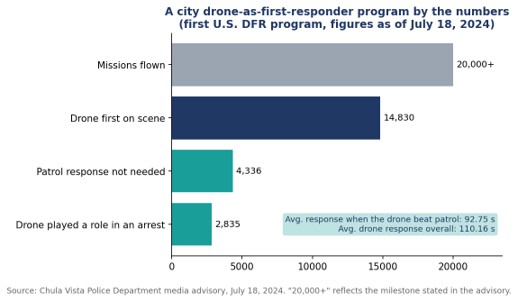
• Drone video streaming sends a UAV camera feed to command staff, dispatchers, and officers in real time, usually over cellular networks. • Chula Vista, California launched the first U.S. drone as first responder program in 2018 and passed 20,000 missions by July 2024. • In that program, drones reached the scene before patrol officers 14,830 times, arriving in an average of 92.75 seconds on those calls. • Combining several cellular connections into one stream reduces the risk that a single congested network interrupts the feed during an incident. |
What is drone video streaming in public safety?
Drone video streaming in public safety is the real-time transmission of a UAV’s camera feed to the people managing an emergency, including command staff, dispatchers, real-time crime center analysts, and officers on their way to the scene. The aim is to give responders eyes on an incident before anyone arrives on the ground.
The model most agencies now study is the drone as first responder, or DFR, program. Instead of launching a drone after officers are already on site, a docked or rooftop drone is sent the moment a 911 call comes in, and its live feed shapes how the rest of the response unfolds. Vendors and integrators have built video workflows designed for drone as first responder programs around that idea, treating the stream as the product and the aircraft as the delivery vehicle.
The practical setup varies by aircraft. Some enterprise drones output video over IP, others over HDMI from a ground controller, and a walkthrough of taking a docked enterprise drone live shows how a compact field encoder can sit between the drone’s video output and the agency’s command center or field devices.
Why does the live feed matter more than the flight itself?
The live feed matters more than the flight because the value of a first responder drone comes from what officers learn before they arrive: which route to take, how many units to send, whether special equipment is needed, and sometimes whether anyone needs to respond at all. Without a stable stream, a fast drone delivers very little.
The clearest public data comes from Chula Vista, California, where the police department began flying drones to emergency calls in 2018 in what it describes as the first program of its kind in the nation. According to the Chula Vista Police Department’s July 2024 program update, the program had passed 20,000 missions. The drone was first on scene 14,830 times, arriving in an average of 92.75 seconds on those calls, and patrol officers did not need to respond 4,336 times because of what the feed showed.
The department’s own examples show why. In one widely reported 2019 call about a man waving a gun, the drone’s camera revealed that the object was actually a lighter before officers made contact. In a 2023 car fire, callers gave the wrong location, and the drone operator used the live video to pinpoint the burning vehicle so officers could pull the driver out seconds before it was engulfed.
How does video get from a drone to the people who need it?
Video gets from a drone to responders through a chain of four links: capture, encoding, transport, and distribution. A weakness at any one of them breaks the whole feed, which is why agencies increasingly evaluate the chain as a single system rather than buying each piece separately.
- Capture: The drone’s gimbal camera, increasingly with thermal capability, produces the raw video at the scene.
- Encoding: An encoder, either on the aircraft, in the dock, or attached to the pilot’s ground station, compresses the feed so it can travel over a mobile network.
- Transport: The compressed stream travels over one or more cellular networks to a receiving server, usually in the cloud or at agency headquarters.
- Distribution: The server pushes the feed to the command center, the real-time crime center, video management systems, and browsers or phones carried by responders in the field.
Distribution is where many early programs struggled. A feed that only reaches the drone pilot’s screen does little for the sergeant deciding where to stage units. LiveU’s LU-REQON1, for instance, is designed to accept multiple IP and HDMI video inputs and pair with a browser-based return feed, so the same drone stream can reach a command center and an officer’s phone at once.
Why is a single cellular connection risky for drone feeds?
A single cellular connection is risky because emergencies tend to happen exactly where networks are under the most strain: crowded events, traffic collisions with onlookers, and large incidents that draw media and residents with phones. When that one connection congests, the drone keeps flying but the feed stalls.
Many drone deployments rely on single-carrier connectivity borrowed from body camera technology, which can struggle to hold a steady feed when that one network is busy. Bonded transmission takes a different approach by combining several cellular links, often across different carriers, into one stream at all times. If one network slows, the others carry more of the load without interrupting the picture. The trade-off is more hardware and more data plans to manage, which agencies weigh against the cost of losing visibility during a critical call.
What regulatory steps shape a drone streaming program?
In the United States, the key regulatory step is FAA authorization to fly beyond visual line of sight, known as BVLOS, because standard rules require operators to keep the drone in view at all times. A DFR program that cannot fly beyond line of sight cannot reach most of the calls it is meant to serve.
Chula Vista’s timeline shows how coverage expands as approvals accumulate. The department joined the FAA’s Integration Pilot Program in November 2018, became the first law enforcement agency authorized to fly BVLOS in an urban area in May 2019, with a range of up to three miles from the launch site, and added a second launch site that August. That second site covered about 33 percent of the city’s area but roughly 70 percent of its priority calls. By March 2021, the department had become the first in the country authorized to launch from anywhere in the city.
Each expansion increases the demand on the video link. More launch sites and longer flights mean more streams, over more varied terrain, reaching more endpoints, which is why connectivity planning tends to grow alongside the flight program rather than being settled once at the start.
What should agencies evaluate before choosing a streaming setup?
Agencies should evaluate latency, resilience under network congestion, integration with existing systems, and governance of how video is stored and shared. Image quality matters, but a sharp picture that arrives late or freezes mid incident is less useful than a steady, slightly softer one.
- Latency: Measure glass-to-glass delay from the drone camera to a responder’s phone, not just to the pilot’s screen.
- Resilience: Test during peak hours and at busy locations, since that is when real incidents strain networks.
- Integration: Confirm the feed can reach the real-time crime center, video management software, and mobile browsers without custom development for each.
- Governance: Set policies for retention, access, and privacy before launch. Chula Vista, for example, publishes historical flight data and states that it does not use DFR for proactive patrol.
Frequently Asked Questions
What is a drone as first responder program?
A drone as first responder program sends a remotely operated drone to an emergency call as soon as it is received, so its live video can guide officers and other responders before they reach the scene.
How fast can a first responder drone reach a scene?
In Chula Vista, California, drones that arrived before patrol officers did so in an average of 92.75 seconds, according to the police department’s July 2024 figures.
How is live video sent from a police drone?
Live video from a police drone is usually compressed by an encoder and sent over one or more cellular networks to a server, which then distributes it to command centers and responders’ devices.
Why do drone programs use bonded cellular connections?
Drone programs use bonded cellular connections because combining several networks keeps the video stable when one network becomes congested during an emergency.

The AI Isn’t Wrong About Your Company. Your Sources Are | Interview with Aia Laser

Should B2B Brands Optimize for Specific AI Engines? How ChatGPT, Google, Perplexity, and Claude Compare

What Is a Blow Molded Case? Process, Materials and Trade-offs Explained

-

 Business Solutions2 years ago
Live Video Broadcasting with Bonded Transmission Technology
-

 Business Solutions1 year ago
The Future of Healthcare SMS and RCS Messaging
-

 Business Solutions2 years ago
2-Way Texting Solutions from Company Message Services
-

 Business Solutions2 years ago
Communication with Analog to Fiber Converters & RF Link Budgets
-

 DSRC Communication2 years ago
The Crossroads of Connectivity: DSRC vs. C-V2X Technologies in Automotive Communication
-

 Business Solutions2 years ago
Wholesale SMS Platforms with OTP Services
-

 Business Solutions2 years ago
Choosing the Right B2B Digital Marketing Agency: A Guide
-

 3D Technology2 years ago
How Multispectral Cameras Advance Book Scanning