


Tech
Global IOR Solutions: Mitigating Regulatory Constraints in Tech Logistics
The expansion of high-value enterprise hardware deployment into emerging global regions presents significant legal, operational, and fiscal hurdles. Technology providers, cloud data center operators, and medical equipment manufacturers frequently face these tough challenges. When routing complex network infrastructure or telecom hardware across international boundaries, organizations encounter strict import restrictions.
Traditional shipping mechanics frequently stall at localized clear zones. This happens because the exporting brand lacks an established, legally recognized corporate entity within the destination country. Consequently, this operational gap compromises deployment schedules. It also creates significant storage penalty vulnerabilities and triggers steep regulatory risks for corporate compliance teams.
Therefore, to bypass these systemic cross-border friction points, international trade networks are increasingly relying on structured, non-vessel operating Importer of Record services. A certified importer of record legally steps in to assume all destination entry compliance liabilities. This setup allows technology developers to expand their hardware footprints seamlessly into new economic markets. Looking at internal logistics reviews like getwayglobaljune1.docx shows how establishing this frontline protection saves networks from catastrophic border delays.
Global Compliance Coverage vs. Operational Risk Indices
A primary bottleneck of relying on legacy freight forwarders is their inability to assume legal ownership of cargo during clearance. This gap shifts all administrative burdens and financial exposure directly back onto the manufacturer. In contrast, utilizing a dedicated entry provider introduces an immediate buffer layer. This buffer handles local tax audits, safety certifications, and customs inquiries cleanly.
The comparison chart below highlights how structured legal representation significantly optimizes global supply chain security:
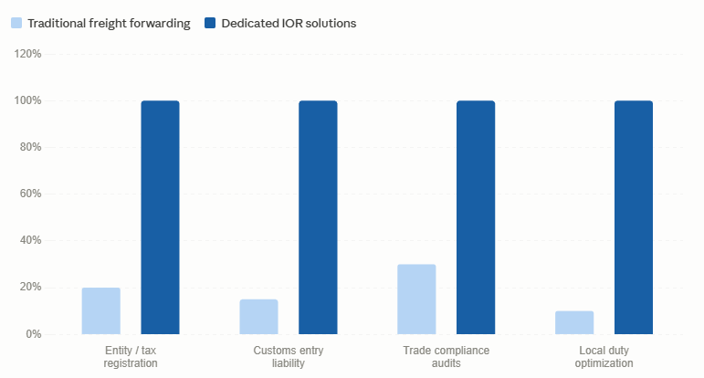
Dual bar chart contrasting global compliance coverage and risk mitigation metrics between traditional freight forwarding and dedicated IOR solutions.
| Logistics Architecture | Traditional Freight Forwarding | Managed Importer of Record (IOR) Framework |
| Destination Legal Liability | Retained fully by the exporter; requires a local entity |
Assumed entirely by the designated IOR provider |
| Customs Documentation Auditing | Basic clerical screening; high rate of entry rejections |
Comprehensive pre-clearance valuation and HTS review |
| EOR / IOR Asset Alignment | Fragmented; requires separate localized agents |
Fully integrated end-to-end global trade management |
| Storage & Delay Penalties | High vulnerability due to frequent documentation stalls |
Minimized via proactive regulatory staging pathways |
| Fiscal Representation Utility | Rarely provided; leaves local tax questions unresolved |
Included as standard to manage import VAT and local duties |
Bypassing Local Entity Requirements Safely
The physical constraint limiting international business expansion is the dense network of local customs laws. Many sovereign nations require an importing entity to maintain a physical, registered corporate office within their territory. Furthermore, this office must hold active local tax registrations before handling high-technology shipments. For example, countries with highly complex import environments frequently turn away unauthorized electronics shipments at the border.
This dynamic means an enterprise software provider trying to ship proprietary server racks to an international client faces massive delays. Fortunately, professional importer of record services completely remove this barrier. By acting as the legally recognized local importer, a dedicated IOR provider clears the hardware under its own entity. This protection allows the tech brand to deploy its hardware assets swiftly without setting up expensive local operations.
The Infrastructure of Managed Asset Clearance
To understand how professional customs routing optimizes these intricate shipping runs, management teams must isolate the core compliance building blocks. At the origin warehouse, trade specialists execute exact Harmonized Tariff Schedule (HTS) classifications. This step ensures proper product labeling while verifying strict compliance with local electronic safety standards.
Next, the provider secures all necessary import permits and handles the upfront payment of destination duties and taxes. As a result, the cargo passes smoothly through customs checkpoints without unexpected financial bottlenecks. Finally, after securing formal customs clearance, the provider coordinates secure last-mile transport directly to the target data center or corporate facility.
Executing Structured Temporary Entry Runs
An evaluation of international trade data shows a critical need for flexible entry options across short-term deployment scenarios:
-
Proof-of-Concept (POC) Installations: Delivering trial network hardware to international clients allows firms to showcase capabilities without triggering long-term tax liabilities.
-
Research and Exhibition Logistics: Moving specialized medical machinery across borders for trade shows requires smooth transport pathways to avoid permanent import assessments.
-
Field Testing Assignments: Deploying diagnostic hardware to remote testing sites demands reliable clearance routines, followed by clean export execution when the project concludes.
In addition, to protect corporate capital during these short-term projects, compliance teams use structured temporary admission procedures. Utilizing specialized customs bonds or structured Carnets allows firms to import high-value hardware for fixed durations safely. Furthermore, this method avoids permanent destination duty costs by ensuring the equipment exits the country cleanly upon project completion.
Conclusion
A professional, asset-light importer of record company has transitioned from an optional logistical luxury into a baseline requirement for international technology deployments. By assuming absolute destination liability and removing the need for localized corporate entities, these providers give tech brands exceptional agility. As international trade regulations grow increasingly strict, utilizing a dedicated compliance framework remains vital. This strategic partnership protects global supply chains, eliminates border delays, and secures critical hardware rollouts everywhere.

The implementation of high-frequency RF over Fiber systems completely resolves the severe physical limitations that traditional copper coaxial wiring introduces within modern telecommunications systems. Modern aerospace, telecommunications, and defense networks routinely deal with complex microwave signals that copper pathways can no longer transmit safely. From advanced satcom downlinks to complex electronic warfare matrices, routing high-frequency signatures over wide operational footprints presents heavy engineering challenges. For example, traditional metallic conductors suffer from extreme, frequency-dependent attenuation that quickly degrades overall signal quality. Furthermore, copper lines serve as passive antennas for electromagnetic interference, which introduces critical security risks into raw data streams.
To overcome these distance-limiting bottlenecks, systems engineers deploy wideband optical conversions to handle high-frequency signals efficiently. By modulating electrical voltages onto an optical carrier wave, fiber subsystems successfully decouple signal loss from physical distance. This conversion method allows design teams to route fragile microwave profiles across multi-kilometer runs with negligible signal degradation. This article evaluates how analog lightwave transport functions, details its strategic importance across modern military grids, and compares physical fiber performance directly with traditional copper media.
Maximum Signal Distribution Radius Without Inline Amplifiers
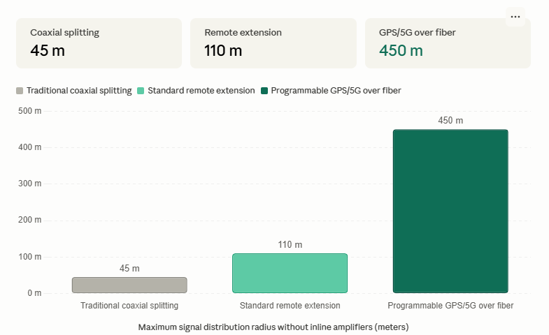
A primary operational bottleneck of copper coaxial lines is the requirement for cascading inline amplifiers to maintain baseline signal visibility over long distances. Each added amplifier introduces extra noise, generates unwanted heat, and creates a potential point of failure within the system architecture. In contrast, deploying optoelectronic conversion units preserves phase accuracy and signal strength across wide distribution radii without needing intermediate power injections.
The bar chart below highlights the maximum transmission footprints achieved across diverse distribution architectures before requiring cascading amplifiers:
Diagram showing the maximum transmission radius in meters without inline amplifiers across coaxial splitting, standard remote extension, and programmable GPS/5G over fiber deployment platforms.
| Operational Parameter | High-Grade Copper Coaxial Cable | Advanced RF over Fiber (RFoF) Systems |
| Signal Loss vs. Frequency | Attenuation scales exponentially with frequency |
Loss is virtually flat and independent of RF frequency |
| Maximum Transmission Range | Restricted to a few meters at frequencies > 18 GHz |
Capable of multi-kilometer runs with negligible loss |
| EMI / RFI Susceptibility | High; requires heavy physical shielding wraps |
Complete dielectric isolation; zero EMI pickup |
| Physical Cable Profile | Heavy, rigid, large diameter; difficult to route |
Thin, flexible, lightweight glass fiber bundles |
| System Signal Security | Prone to near-field inductive signal interception |
Secure; optical fields are fully contained inside the core |
Overcoming High-Frequency Attenuation Barriers
The physical constraint limiting high-grade copper wires stems directly from the skin effect at elevated frequencies. As radio signals scale up into microwave and millimeter-wave bands like 18 GHz or 40 GHz, electrical current is forced to travel exclusively along the outermost layer of the conductor. Consequently, this physical compression drives up copper resistance exponentially.
This internal restriction means a standard low-loss coaxial cable running at 40 GHz loses almost all usable signal strength within just a few meters. This rapid dissipation complicates the deployment of radar arrays, satellite ground stations, and distributed antenna architectures. Luckily, wideband analog optical conversion completely bypasses this distance barrier. It provides a completely flat attenuation profile that guarantees uniform signal preservation across the entire frequency spectrum.
Lightwave Modulation Mechanisms in Fiber Cores
To understand how RF over Fiber systems execute this low-loss transport, engineers must isolate the underlying electro-optic conversion blocks. At the transmitter assembly, incoming electrical radio waves modulate a low-noise laser beam via direct or external optical modulation paths. This modulated light signal travels across single-mode fiber-optic glass threads that offer native dielectric isolation. As a result, the signal path remains completely immune to grounding loops, lightning strikes, and adjacent radio frequency interference.
At the receiver end, a highly sensitive photodiode converts the light wave back into a replica of the original RF electrical signal. Because single-mode optical fiber loses less than 0.5 dB per kilometer regardless of carrier frequency, operators can link distant antenna elements directly to centralized hubs. This direct interlinking removes the need for expensive, localized signal down-conversion hardware at the masthead.
Strategic Deployment Environments
A comprehensive analysis of global market data highlights a clear industry shift toward analog optical lines across high-reliability deployment environments:
-
Satellite Earth Stations: Interconnecting distributed antenna dishes directly to central shelter rooms allows operators to centralize receivers while keeping physical signal dissipation low.
-
Radar and Electronic Warfare (EW): Routing sensitive microwave chirps across compact aircraft fuselages and naval hulls occurs safely without picking up local engine noise or electrical power distortions.
-
Broadcast and Wireless Networks: Distributing high-frequency master clock signatures over wide venue systems ensures microsecond-level phase accuracy across all connected nodes.
To implement these high-frequency paths, design teams deploy specialized programmable RF over Fiber links to transport microwave signatures up to 40 GHz without signal degradation. Furthermore, utilizing integrated low-noise analog optical subsystems allows networks to maintain excellent carrier-to-noise ratios over multi-kilometer spans.
Conclusion
Analog RF over Fiber systems have transitioned from a specialized niche solution into a core requirement for high-frequency communication architectures. By removing the distance constraints of copper coax and offering complete immunity to electromagnetic noise, lightwave transport provides system designers with unmatched architectural freedom. As global data requirements push operational bandwidths higher into the millimeter-wave spectrum, deploying dedicated optical links remains vital to protect signal integrity across critical defense and telecommunications infrastructure.
Tech
High-Resolution Photogrammetry in Aerial Mapping: Optimizing Spatial Data Accuracy and Flight Efficiency
High-resolution photogrammetry technology resolves the severe operational bottlenecks that traditional imaging hardware can no longer handle within modern engineering and geospatial surveying sectors. A single infrastructure corridor inspection or topographic survey routinely covers thousands of hectares of varying terrain. Furthermore, standard environmental surveying projects regularly demand hundreds of parallel flight passes, a requirement that generates massive quantities of fragmented data. Industrial utility corridors—such as pipelines, railway networks, and power grids—require continuous, high-altitude monitoring. In these scenarios, any reduction in image sharpness leads to geometric errors during post-processing. Consequently, the sheer volume of raw data captures stretches engineering workflows to their limits, while an inaccurate point cloud reconstruction can cause severe structural design failures or costly project delays.
Dedicated metric imaging systems have emerged as the definitive structural response to these geospatial challenges. By engineering metrically calibrated, large-format and medium-format sensors explicitly for flight payloads, modern setups automatically minimize lens distortion, optimize spatial resolution, and maximize coverage area per flight line. Therefore, this structural integration drastically reduces the physical demands placed on flight crews and processing teams while simultaneously enhancing the absolute accuracy of the final topographic models. This review evaluates how high-resolution aerial imaging functions, why it has become the benchmark for commercial surveying operations, and what optical mechanics distinguish dedicated metric systems from standard commercial drone cameras.
What Is High-Resolution Aerial Photogrammetry?
High-resolution aerial photogrammetry involves the automated collection and processing of overlapping aerial images to calculate precise three-dimensional coordinates of physical objects on the Earth’s surface. Unlike generic consumer-grade photography or basic video mapping, specialized metric data collection relies on sensor platforms constructed specifically to maintain internal geometric stability under intense flight vibrations and wide temperature fluctuations.
Advanced metric platforms distinguish themselves by utilizing sensor dimensions that far exceed standard 35mm formats. These large-format and medium-format configurations allow surveying systems to resolve sub-centimeter Ground Sample Distance (GSD) from significantly higher operating altitudes. Furthermore, integrated global leaf shutter mechanisms eliminate the rolling shutter distortions common in standard drone hardware, ensuring that each pixel is exposed simultaneously and capturing an unwarped image plane even at high cruise velocities.
The Scale of the Aerial Surveying Challenge
The operational dimensions of large-scale mapping projects present major logistical and financial hurdles. In traditional aerial surveying, utilizing standard 24-megapixel or 50-megapixel sensors means that to achieve a high spatial resolution, aircraft must operate at low altitudes and tight line spacings. This configuration increases the total flight lines required to achieve adequate side and forward overlap, which directly translates to extended flight hours, increased fuel expenditure, and prolonged exposure to hazardous weather windows.
This reality exposes a clear operational constraint: lower-resolution payloads degrade surveying profitability by multiplying field capture times and increasing data complexity. High-resolution sensor integration fundamentally shifts this dynamic. By scaling sensor capabilities to 100 megapixels or 150 megapixels, mapping groups can expand their ground swath width substantially, transforming what used to be a multi-day flight operation into a streamlined, single-pass execution.
Required Flight Paths by Sensor Class (Equal GSD)
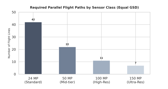
To understand how pixel density translates into operational financial savings, surveying teams must analyze flight path requirements. Increasing sensor resolution directly widens the lateral ground swath covered during a single pass. As a result, the aircraft requires far fewer parallel passes to map a fixed surface area, saving significant flight time and fuel.
The column chart below illustrates how switching to an advanced aerial mapping camera dramatically minimizes total flight line overhead:
Bar chart showing the required parallel flight paths by sensor class to achieve equal Ground Sample Distance, demonstrating that a twenty-four megapixel standard camera requires forty-two lines, while a one hundred and fifty megapixel ultra-res metric camera requires only seven lines.
| Feature / Metric | Standard Commercial Sensors | Specialized Metric Mapping Systems |
| Data Capture Width | Narrow ground swath; requires high line overlap |
Ultra-wide ground swath; maximizes coverage per pass |
| Shutter Architecture | Rolling electronic shutter; prone to movement blur |
Global leaf shutter; eliminates high-speed geometric distortion |
| Calibration Stability | Variable; changes with temperature and vibrations |
Permanently locked metric calibration; verified parameters |
| Altitude Capabilities | Restricted to low altitudes to maintain acceptable GSD |
Capable of high-altitude operations with sub-centimeter GSD |
| Processing Complexity | High volume of images; demands extensive processing time |
Minimal, high-density images; drastically shorter mosaic times |
| Structural Adaptability | Limited to specific consumer drone mounts |
Flexible; optimized for manned aircraft and payload drones |
| Spectral Options | RGB only; requires independent sensor changes |
Seamless co-registered RGB and 4-band imagery options |
Core Metric Camera Capabilities for Geospatial Applications
The following technical attributes represent the baseline criteria for professional-grade imaging integration within modern commercial mapping and surveying applications:
-
Calibrated Metric Optics: Factory-locked lens elements eliminate internal structural shifting, ensuring consistent focal length parameters across thousands of flight cycles.
-
High Dynamic Range (HDR): Advanced pixel architectures preserve fine shadow detailing and highlight definition simultaneously, which is critical when mapping high-contrast environments.
-
Integrated Hardware Synchronization: Microsecond-level integration links the camera shutter, flight management systems (FMS), and onboard GNSS/IMU receivers to provide precise orientation data.
-
Multi-Band Sensor Formats: Systems support simultaneous RGB and Near-Infrared (NIR) data capture to deliver accurate four-band imagery for agricultural and environmental monitoring.
-
Unmatched Shutter Durability: Industrial-grade mechanical leaf shutters survive hundreds of thousands of actuation cycles without requiring frequent maintenance intervals.
Payloads and Platforms: A Critical Architecture Decision
A primary decision point for commercial surveying operations involves choosing between medium-altitude manned aircraft integrations and lightweight UAV payload configurations. Historically, ultra-high-resolution mapping was restricted to large, manned aircraft due to the weight and power requirements of heavy, large-format camera enclosures. While highly efficient for continental-scale mapping, this approach introduces substantial operational overhead, fuel costs, and mobilization delays for regional project work.
The emergence of ultra-lightweight, medium-format 3d mapping camera designs has resolved this operational compromise. Modern 100MP and 150MP architectures have been miniaturized into specialized compact enclosures, allowing them to be deployed as a standard uav camera payload configuration. This engineering milestone brings true large-scale photogrammetry accuracy down to localized drone mapping and surveying workflows, providing an agile, rapidly deployable solution that eliminates manned aircraft costs while preserving metric integrity.
Deployment Environments: Where Specialized Imagery Delivers Value
Industrial metric imaging systems provide the most reliable operational returns in complex environments characterized by strict accuracy requirements and challenging flight windows:
-
Topographic and Cadastral Surveying: Creating highly accurate base maps for land administration, property boundaries, and civil engineering designs.
-
Urban 3D Digital Twin Development: Capturing high-density oblique imagery over dense metropolitan sectors to construct distortion-free 3D city models.
-
Volumetric Open-Pit Mining Analysis: Delivering reliable, repeatable point clouds to calculate stockpile volumes and excavation rates safely from the air.
-
Large-Scale Corridor Mapping: Monitoring linear assets like transcontinental pipelines, highway networks, and electrical transmission grids efficiently.
What to Look for in an Aerial Surveying Platform
Procurement teams and engineering directors evaluating new aerial surveying platforms should rigorously assess lens-to-sensor integration, ensuring the optical elements explicitly match the high-resolution pixel pitches to prevent edge softness. Furthermore, operational weight and power efficiency must fall within the maximum takeoff weight (MTOW) limits of target UAVs to prevent degrading flight times. Software workflow integration must also be assessed to see how seamlessly the native camera software links with post-processing suites to optimize orthophoto generation. Finally, real-world environmental protection should be verified to confirm that the imaging enclosure features an industrial IP rating to withstand high thermal variations encountered during flight. Choosing a platform engineered around physical pixel density and mechanical calibration directly removes the risks associated with unreliable field captures, proving that long-term surveying success is built on optical precision.
Conclusion
High-resolution photogrammetry has established itself as an indispensable core component of modern aerial surveying and geospatial analysis. The combination of massive pixel counts, rigorous geometric calibration, and flexible deployment across drone and aircraft platforms makes metric hardware an essential asset for firms managing tight project windows and strict data criteria. As the global demand for accurate 3D spatial models and real-time digital twins continues to accelerate, the operational gap between consumer-grade camera arrays and highly sophisticated metric platforms will continue to expand—solidifying high-resolution optical solutions as an absolute necessity for competitive geospatial operations.
Best UAV Encoders 2026: Top Drone Video Encoder Solutions Compared
Selecting a UAV encoder for a defense or security platform is not a decision that can be made on datasheet figures alone. A drone encoder that performs adequately in a controlled RF environment may fail under electronic warfare conditions. A unit with impressive compression numbers may still add unacceptable weight to a small tactical UAV. This review compares the leading drone video encoder solutions available in 2026, evaluated across five criteria that matter most to systems engineers and program managers: size-weight-and-power (SWaP), end-to-end latency, codec and resolution support, onboard AI capability, and defense/security suitability. The goal is to provide an objective overview of a competitive market, grounded in publicly available product information.
This article covers four representative categories of drone encoder solutions: defense-specialized miniature AI-integrated platforms, broadcast-derived professional encoders, FPGA-based configurable hardware, and software-defined encoder stacks. Readers are encouraged to evaluate options against their own platform requirements.
Evaluation Criteria
Before comparing specific solutions, it is worth establishing the evaluation framework. A professional-grade drone encoder should be assessed on:
- SWaP: Total size, weight, and power draw — critical for small unmanned platforms with fixed payload budgets.
- End-to-end latency: Glass-to-glass latency from sensor capture to display, measured under load.
- Codec support: Specialized hevc hardware encoding is now a baseline; H.264 backward compatibility is frequently required.
- Onboard AI: Ability to run detection, classification, or tracking algorithms on the payload without ground-based servers.
- Environmental ruggedization: Compliance with MIL-STD or equivalent environmental standards for vibration, temperature, and EMI.
- Multi-stream support: Simultaneous encoding of multiple video channels from different sensors.
The UAV Encoder Market in 2026: A Brief Overview
The UAV encoder market has bifurcated into two distinct segments. One segment — largely driven by the broadcast and live-streaming industry — produces high-quality encoders optimized for studio and outdoor events. These devices typically prioritize bitrate fidelity and compatibility with streaming platforms over SWaP and latency. According to Streaming Media Magazine, broadcast encoders have improved dramatically in H.265 support, but their form factors (often 200–500 g and 10–25 W) make them unsuitable for tactical UAV payloads that must stay under 60–100 g and 8–10 W.
The second segment comprises defense-specialized hardware developers who have built encoder solutions from the ground up for airborne, SWaP-constrained environments. These solutions sacrifice some absolute bitrate performance for dramatic reductions in size and power, while adding features such as ruggedization, onboard AI, and electronic warfare resilience. This is the segment where procurement decisions for tactical drone platforms should focus.
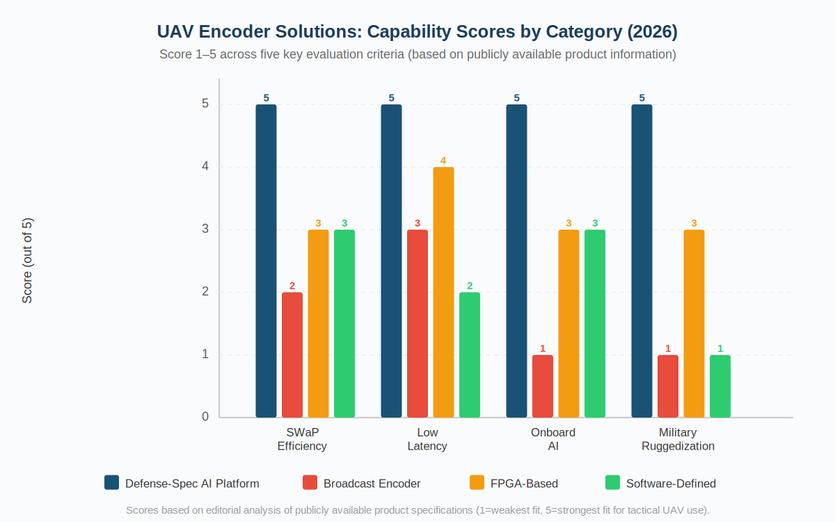
Comparison: Leading UAV Encoder Solutions
The comparison below evaluates four representative solutions. Ratings are based on publicly available product information and reflect performance profiles rather than absolute rankings.
| Criteria | Maris-Tech (Jupiter / UAV Encoders) | Broadcast-Derived Pro Encoders | FPGA-Based Configurable HW | Software-Defined Stacks |
| SWaP Optimization | High — purpose-built for UAV payload budgets | Low — designed for fixed/ground installations | Medium — configurable but often larger than needed | Medium — depends on host compute platform |
| End-to-End Latency | Ultra-low (<80 ms target) | Moderate (100–300 ms typical) | Low–Medium (varies by configuration) | Variable (often >150 ms on modest hardware) |
| H.265 / HEVC Encoding | Hardware-accelerated, standard | Supported, often hardware | Configurable; hardware H.265 available | Software H.265; hardware depends on GPU |
| Onboard AI Capability | Integrated (edge AI acceleration) | Not available | Requires custom IP core development | Depends on host platform GPU |
| Multi-Stream Support | Yes, multi-channel simultaneous | Limited; typically single-channel | Configurable with additional FPGA resources | Depends on CPU/GPU resources |
| Military Ruggedization | Yes — MIL-STD environments | No — commercial grade | Varies — some industrial-grade options | No — inherits host platform rating |
| Defense Customer Validation | Yes — governmental and defense customers | No specific defense validation | Used in some defense-adjacent programs | Limited; primarily commercial applications |
Source: Publicly available product specifications and company websites.
Defense-Specialized UAV Encoders: The Case for Purpose-Built Hardware
Defense and security procurement managers consistently find that broadcast-derived or commercial encoders require significant modification — or are simply unsuitable — for UAV integration. The gap is most acute in three areas: SWaP, latency under electronic warfare conditions, and onboard AI.
Specialized tech providers address all three directly through dedicated uav encoder product lines, which have been specifically engineered for the UAV environment. High-performance drone encoder platforms are designed to withstand vibration, temperature extremes, and RF interference common in UAV operations — constraints that commercial video hardware does not account for. Systems requiring high physical flexibility deploy miniature uav encoders to comfortably fit specialized layouts while maintaining multi-stream drone encoder pipelines intact.
FPGA-Based Solutions: Flexibility vs. Integration Complexity
Field-programmable gate array (FPGA) based encoder solutions offer configurability advantages — a program can, in theory, update the encoder’s processing pipeline to accommodate new codecs or AI models via firmware. In practice, however, FPGA development requires specialized engineering expertise and extended development timelines. For programs with defined requirements and tight delivery schedules, an integrated, validated solution typically offers a lower total integration cost than a flexible but complex FPGA platform.
Software-Defined Encoding: When It Works and When It Doesn’t
Software-defined encoding on embedded compute platforms (ARM SoCs, Nvidia Jetson, etc.) has become more capable as chip performance has increased. For commercial inspection or mapping drones where latency targets are relaxed (under 300 ms is typically acceptable), software stacks offer integration flexibility. For tactical defense applications requiring sub-100 ms latency, dedicated hardware encoding is still necessary — software encoding on embedded platforms introduces encode latency of 50–150 ms before transmission even begins.
Scoring Summary
| Category | Defense-Spec Hardware | Broadcast Pro | FPGA-Based | Software-Defined |
| Tactical UAV Suitability | ★★★★★ | ★★☆☆☆ | ★★★☆☆ | ★★☆☆☆ |
| Commercial/Inspection UAV | ★★★★☆ | ★★★☆☆ | ★★★☆☆ | ★★★★☆ |
| Integration Simplicity | ★★★★☆ | ★★★★☆ | ★★☆☆☆ | ★★★☆☆ |
| Onboard AI Readiness | ★★★★★ | ★☆☆☆☆ | ★★★☆☆ | ★★★☆☆ |
| SWaP Efficiency | ★★★★★ | ★★☆☆☆ | ★★★☆☆ | ★★★☆☆ |
Note: Ratings are editorial assessments based on publicly available product information. ★★★★★ = strongest fit for category.
Conclusion: Which UAV Encoder Is Right for Your Application?
For tactical defense and security applications where SWaP, latency, onboard AI, and military ruggedization are all required simultaneously, purpose-built defense-specialized platforms have a clear structural advantage over broadcast, FPGA, or software alternatives. High-grade architectures combine multi-channel hd video encoder systems alongside ai embedded systems to aggregate, analyze, and encode incoming sensor data right at the edge.
Broadcast-derived encoders remain the better choice for studio and event production. FPGA solutions suit programs with extended development timelines and highly customized processing requirements. Software-defined stacks work well for commercial drones with relaxed latency targets. Understanding this segmentation is the first step to making the right procurement decision.
For competitive product information, readers may also refer to Teradek’s UAV encoder offerings as a reference point for broadcast-heritage solutions in this market.
Global IOR Solutions: Mitigating Regulatory Constraints in Tech Logistics
High-Frequency RF over Fiber Systems: Breaking the Coaxial Bandwidth Barrier
Industrial IoT Gateways for Remote Asset Monitoring: What Utilities and Infrastructure Operators Need to Know

-

 Business Solutions2 years ago
Live Video Broadcasting with Bonded Transmission Technology
-

 Business Solutions1 year ago
The Future of Healthcare SMS and RCS Messaging
-

 Business Solutions2 years ago
2-Way Texting Solutions from Company Message Services
-

 Business Solutions2 years ago
Communication with Analog to Fiber Converters & RF Link Budgets
-

 DSRC Communication1 year ago
The Crossroads of Connectivity: DSRC vs. C-V2X Technologies in Automotive Communication
-
Electronics3 years ago
AI Modules and Smart Home Chips: Future of Home Automation
-

 Business Solutions2 years ago
Wholesale SMS Platforms with OTP Services
-

 Business Solutions2 years ago
Aerial Wind Turbine Inspection with Advanced Camera Drones