


Business Solutions
VC Israel vs. Global Pitch Expectations: How Presentations Differ by Market
In the world of startup financing, where ideas become companies and companies become global catalysts for innovation, the first meeting between founders and investors is pivotal. How a pitch is structured, what the audience expects, and even the cultural context can dramatically influence whether a startup receives funding or is dismissed. Among global entrepreneurial hubs, the venture capital environment in Israel stands out for its distinctive style and expectations. In this article, we explore how VC Israel standards compare to broader global expectations, particularly in how founders prepare, deliver, and succeed with venture capital presentations.
To understand the nuances between pitching in Israel versus other markets like the United States, Europe, or Asia, we must first examine the defining characteristics of these ecosystems. What do investors prioritize? Which metrics carry the most weight? How much emphasis is placed on storytelling versus technical depth? And crucially, how should entrepreneurs adapt their pitch decks depending on their audience?
The Cultural Foundations of Pitching
Israeli Pitch Culture: Direct, Data-Driven, and Fast
The Israeli startup scene, often referred to as “Startup Nation,” is renowned for its rapid pace, technical talent, and no-nonsense approach to business. Investors in Israel, including both local firms and global VCs with Israeli portfolios, are known for their direct questioning, deep technical due diligence, and skepticism toward overhyped narratives.
This comes from a broader cultural ethos. Israeli communication styles tend to be blunt and straightforward, with less tolerance for inflated language or polished but shallow pitches. Founders are expected to demonstrate deep mastery of their technology and market from the first slide.
For startups preparing their pitch decks, resources such as venture capital presentations from seasoned investors can provide useful templates and expectations common in the local market. These presentations often highlight:
- Clear articulation of the problem and solution.
- Early evidence of technical feasibility.
- Deep understanding of competitors and industry structure.
- Realistic financial projections rooted in verified assumptions.
Global Pitch Culture: Narrative, Scale, and Market Vision
In contrast, global pitch expectations, particularly in Silicon Valley, often emphasize visionary storytelling alongside numbers. Investors like those in Sequoia Capital, Andreessen Horowitz, or SoftBank frequently look beyond the current product to the potential scale and disruption a company can create.
Here are characteristics often associated with global pitch culture:
- Story-first approach: Founders build an emotional narrative about the world they want to create.
- Market opportunity emphasis: The larger the total addressable market (TAM), the better.
- Scalability and growth potential: Even early-stage companies pitch future expansion with confidence.
- Branding and Design: Slide decks are often polished with professional aesthetics.
This doesn’t mean global investors ignore data, far from it, but they balance hard numbers with compelling vision. For many early global stage investors, the pitch is a tool to gauge the founder’s big picture thinking, not just their current traction.
Structure and Content Expectations: Israel vs. Global Markets
Although pitch deck structures share many elements worldwide, the order, emphasis, and depth of certain sections differ between markets.
Common Global Pitch Deck Structure
Across many regions, especially in the U.S. and Europe, a commonly accepted pitch deck order includes:
- Problem Statement
- Solution/Product
- Market Size (TAM/SAM/SOM)
- Business Model
- Traction and Metrics
- Team
- Financial Projections
- Competitive Advantage
- Ask/Funding Needed
This order is not arbitrary. It reflects a flow from why the world needs your product to how you will make money and grow. Influential guides such as those from Harvard Business School and Y Combinator reinforce this structure
Israeli Pitch Deck Expectations
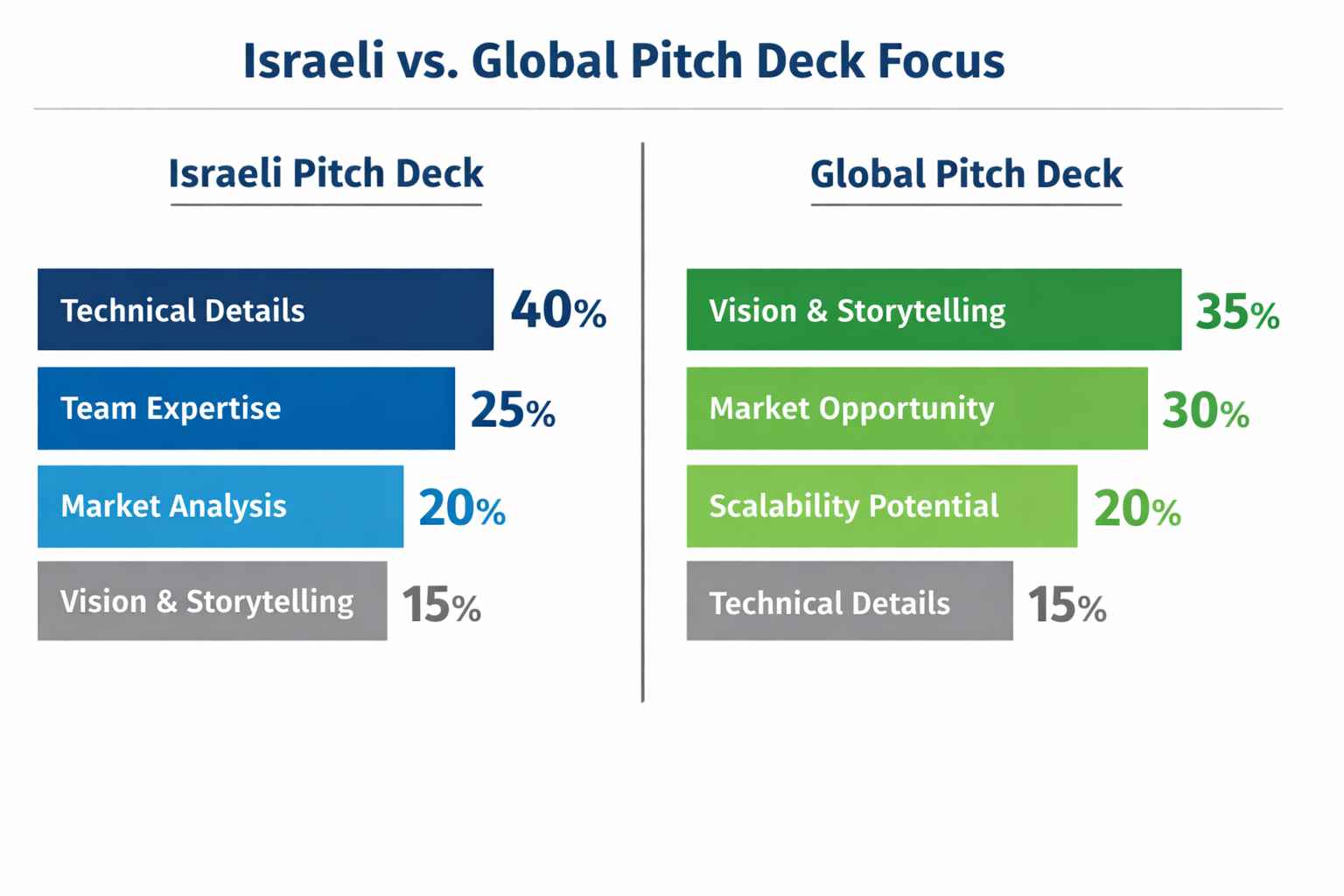
While many Israeli founders use a similar structure, investors often invert or emphasize sections differently:
- Technical Detail Early: Israeli investors frequently want to see technical feasibility early in the deck. They may request product architecture, prototypes, or validation data immediately after the problem statement.
- Revenue Model Later: While global decks place the business model near the front, Israeli pitch decks sometimes delay detailed monetization strategies in favor of showcasing technology superiority.
- Focus on Team Competence: The team section in an Israeli pitch deck often goes deeper, with founders expected to justify why they specifically are the right people to build this product, supported by technical resumes and benchmarks.
This divergence reflects the general sentiment of Israeli VCs that execution excellence, especially on the technical side, is the strongest predictor of success.
Preparation and Due Diligence: What Investors Look For
Israeli Investor Priorities
Investors in Israel often approach pitches with a “trust but verify” mindset. Rather than being convinced by optimistic forecasts, they want hard evidence.
Before a pitch, founders should be ready with:
- Technical proofs and validation tests.
- Detailed TAM breakdowns by real data (not just estimates).
- Competitor product comparisons with technical differentiation.
- Clear operational plans showing how milestones will be achieved.
Often, Israeli firms conduct intensive due diligence immediately after the first meeting, meaning founders must be prepared even before they enter the room.
Global Investor Priorities
Globally, while investors care about due diligence, they often allow for a vision-first pitch with iterative exploration afterward. Many global investors will:
- Accept early-stage pitch decks without full financials.
- Focus more on traction and team vision than completed development.
- Place greater weight on market disruption potential.
This doesn’t mean due diligence is lax, far from it, but it unfolds more systematically, often after initial term sheet discussions.
For example, global investors in biotech or AI will first seek the big picture, then dive into specifics during formal due diligence. A resource explaining how global VC diligence works can be found at Investopedia.
Communication Style: Directness, Storytelling, and Humor
Israeli Pitch Tone
Israeli founders often adopt a direct, straightforward, blunt approach without unnecessary elaboration. Presentations are typically high-content, low-fluff. Israeli investors may interrupt frequently with questions that test assumptions, a cultural preference that values real substance above polished narratives.
Humor can be used, but sparingly and with the expectation that it won’t replace hard information.
Global Pitch Tone
Many global markets, particularly in North America, value storytelling. Founders are encouraged to build an emotional arc:
- Start with a compelling problem.
- Introduce characters (i.e., target users).
- Describe transformation through innovation.
This style borrows from marketing and business storytelling frameworks such as those described in the Stanford Graduate School of Business Pitch Materials.
Supporting Materials: What to Bring
In Israel
Israeli investors expect highly technical appendices ready for immediate review. These may include:
- Architecture diagrams
- Prototype data
- Benchmarks and performance metrics
- Customer testimonials (especially for B2B)
Founders might also bring metrics dashboards or IDE activity logs anything that proves work done, not promises made.
Global Expectations
Globally, executives often prepare:
- Market research documents
- Unit economics breakdowns
- TAM/SAM/SOM visualizations
- Surveys or user feedback
- Branding assets
The goal is to support the pitch with both logic and narrative reinforcement.
Common Mistakes by Non-Local Founders
When founders from outside Israel present to local investors, they often make predictable mistakes:
Overemphasis on Vision Without Depth
Investors may perceive highly narrative pitches lacking data as vague or unprepared, especially in tech-intensive sectors.
Skipping Technical Specifications
Israeli investors expect rigorous technical clarity. Even for founders in non-technical roles, supporting technical co-founders should be present and prepared to answer deep questions.
Underestimating Competition
Global markets have many large players. Without direct comparisons showing a technical edge, Israeli investors may assume a product will be commoditized.
How Founders Should Adapt
If pitching in Israel:
- Lead with data and technology.
- Be ready to answer detailed questions at any moment.
- Present clear differentiation from competitors.
If pitching to global investors:
- Build a strong narrative about why the world needs your product.
- Emphasize market growth and potential scale.
- Balance vision with logic, not one over the other.
A useful strategy is to create two versions of your deck:
- A technical, data-heavy version for highly analytical audiences.
- A vision-driven version for audiences that value storytelling.
Both should contain the same core facts, but their presentation and emphasis must differ.
Tools and Resources for Pitch Preparation
Israeli and Global Templates
- VC Israel Deck Examples: The venture capital presentations available from investor groups provide real-world formats common in the Israeli market.
- Y Combinator Pitch Deck Advice: A widely cited global benchmark, the YC pitch deck template offers direction on essential slides for early-stage startups.
- Harvard Business School Guide to Pitching: Offers a thorough framework for preparing investment presentations.
Final Takeaways: Balancing Local Norms with Global Standards
As entrepreneurship becomes ever more global, founders must become bilingual in presentation styles:
- Know your audience: Research investor preferences by region.
- Customize your deck: One size does not fit all.
- Balance story and substance: Both matter in different proportions.
- Practice adaptability: Investors will drive the conversation where they want it.
- Leverage local resources: Formats like VC Israel and associated materials help align expectations.
Whether you’re pitching in Tel Aviv, New York, Berlin, or Singapore, understanding cultural expectations from the direct, data-driven style of Israeli investors to the narrative-rich approach of global markets can dramatically improve your odds of success.

Business Solutions
Optical Delay Lines: The Precision Solution Reshaping Radar and Altimeter Testing
Summary: Radar and altimeter systems must be rigorously tested and calibrated before deploymen-but transmitting live RF energy to simulate target returns is impractical, hazardous, and often impossible in a laboratory or depot environment. This article explains how optical delay lines (ODLs) solve this fundamental challenge, how they work, why fiber-based delay lines outperform electronic alternatives, and how RFOptic’s specialized ODL solutions support radar and altimeter testing programs across defense and aviation markets.
Radar and altimeter testing is one of the most technically demanding areas in defense electronics validation. Systems must be verified to perform accurately across a range of simulated target distances, velocities, and environments-yet doing so by physically placing reflecting targets at the required distances is seldom feasible. The solution lies in optical delay lines, a technology that uses the fixed propagation speed of light in optical fiber to introduce precisely controlled time delays into an RF signal, simulating the time-of-flight of a radar return at a specified range.
The Testing Problem: Why You Cannot Simply Transmit to a Real Target
A radar system determines the range of a target by measuring the round-trip time of a transmitted pulse. An altimeter determines altitude by measuring the time for the transmitted signal to reflect off the ground and return. In both cases, the fundamental measurement is time-of-flight -and testing this measurement requires introducing a known, accurate delay between the transmitted signal and the simulated return.
In field testing, this can be done by physically placing a reference reflector at a known distance. But field testing is expensive, weather-dependent, logistically complex, and often impossible for airborne altimeters (which would require flight testing to validate each range point) or for classified radar systems that cannot be operated in environments where frequency emissions are monitored or regulated. Depot-level maintenance and factory acceptance testing require a bench solution.
Electronic delay lines-switched networks of lumped inductors and capacitors, or surface acoustic wave (SAW) devices-have historically been used for this purpose. But they carry significant limitations: limited frequency range, high insertion loss, temperature-dependent performance, and the inability to cover the multi-microsecond delays needed to simulate distant targets without cascading multiple stages and accumulating noise and distortion.
How an Optical Delay Line Works
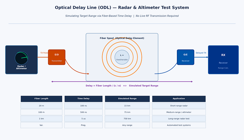
An optical delay line converts the RF signal to be delayed into an optical signal using an electro-optic modulator or laser diode, routes that optical signal through a calibrated length of single-mode optical fiber, then reconverts it back to an RF signal at the output using a photodetector. Since light travels through fiber at approximately 2×1⁰⁸ meters per second (about two-thirds of the speed of light in vacuum), a specific fiber length produces a very precise and stable delay.
For example, approximately 100 meters of fiber produces a delay of around 500 nanoseconds-equivalent to a radar range of approximately 75 kilometers in a monostatic radar configuration. Variable delay lengths can be achieved through switched fiber spools, allowing test equipment to simulate targets at multiple programmable ranges without moving any physical hardware.
The key performance advantages of fiber-based delay lines compared to electronic alternatives are:
• Extremely low loss: optical fiber introduces negligible signal loss per unit length compared to coaxial cable or electronic delay elements at microwave frequencies.
• Frequency independence: the delay is determined purely by the fiber length, not the frequency of the signal. The same ODL works equally well at 1 GHz and at 40 GHz, making it suitable for multi-band radar and wideband altimeter testing.
• Excellent phase stability: fiber delay is not affected by electromagnetic interference and shows very low thermal drift compared to electronic delay networks.
• Scalability: very long delays (microseconds to tens of microseconds) equivalent to hundreds or thousands of kilometers of range-are achievable simply by using more fiber, without cascading lossy electronic stages.
• Electrical isolation: optical fiber passes no DC current and provides complete galvanic isolation between the input and output RF ports, eliminating common-ground interference paths in complex test setups.
Variable and Programmable Optical Delay Lines
The most operationally useful ODL systems offer variable or programmable delay-the ability to switch between multiple discrete delay values to simulate different target ranges. This is achieved through optical switching networks that connect the RF signal to different fiber spools of different lengths, or through continuous variable delay mechanisms using motorized fiber stretchers or optical path length adjustment.
Programmable delay lines are essential for acceptance testing of radar systems that must perform across the full specified range envelope. Rather than resetting physical hardware for each range point, the test engineer selects the desired delay from the ODL’s control interface, and the system switches to the appropriate fiber path within milliseconds. For automated production test environments, this enables rapid, software-controlled multi-point range calibration.
According to the IEEE Transactions on Microwave Theory and Techniques, optical delay line technology has advanced considerably with the integration of programmable switching and temperature compensation, making modern ODL systems suitable for demanding calibration environments where measurement uncertainty must be minimized.
Altimeter Testing: A Specialized Requirement
Radio altimeters-used in commercial aviation, military aircraft, and UAVs to measure height above terrain-are safety-critical systems with stringent testing requirements. Regulatory bodies including the FAA and EASA require verification of altimeter accuracy across the full operating altitude range, typically from near-zero to several thousand feet. Testing each altitude point requires introducing the corresponding time delay between the transmitted altimeter signal and the simulated ground return.
Modern radar altimeters typically operate in the 4.2–4.4 GHz frequency band, though next-generation systems and those for unmanned platforms span wider ranges. Key testing parameters include:
• Absolute accuracy: the altimeter must measure altitude to within a defined tolerance across the full range.
• Response time: the altimeter must update its reading within a specified latency when altitude changes rapidly-important for terrain-following and automatic landing systems.
• Interference immunity: with 5G networks now deployed in the 3.7–4.2 GHz C-band in many countries, regulatory concerns about altimeter interference have made test coverage of adjacent-band interference scenarios a new requirement.
An optical delay line test system for altimeter applications must cover the altimeter’s full altitude range (typically equivalent to delays from a few to several hundred nanoseconds), handle the altimeter’s specific frequency band, and provide calibrated, repeatable delay values. For aircraft integration testing, the system must also operate reliably in the electromagnetic environment of an avionics test bench.
RFOptic’s Optical Delay Line Solutions
RFOptic offers customized low and high frequency optical delay line solutions for testing and calibrating radar and altimeter systems. The company’s ODL product line is described as one of its core competencies, offering both standard and application-specific configurations.
RFOptic provides both fixed and programmable delay configurations, with the following key characteristics as described on their platform:
• Coverage from low frequency through high-frequency microwave and mmWave bands, supporting both current-generation radar and altimeter systems and next-generation wideband applications.
• Customized ODL systems developed to customer specifications, including integration with specific test equipment interfaces and control software.
• Online request-for-quote tool for customized ODL and altimeter ODL systems, supporting design consultation from the earliest project stage.
• Subsystem integration: RFOptic’s ODLs can be integrated into complete radar and altimeter test subsystems, combining the delay function with signal conditioning, switching, and management interfaces.
RFOptic’s value proposition emphasizes that in the pre-sales stage, the company builds solutions tailored to customer needs, including simulations that predict link behavior-particularly important for ODL systems where target delay accuracy and dynamic range must be verified analytically before hardware is built.
Emerging Applications: UAV Altimeters and Radar Testing
The rapid growth of unmanned aerial systems (UAS/UAV) has created a new generation of altimeter testing requirements. Drone altimeters are smaller, lighter, and often operate in different frequency bands than traditional aviation altimeters. They must be validated for low-altitude terrain-following, precision landing approaches, and operation in spectrum-contested environments. The same fundamental principle applies: fiber-based optical delay lines provide the most accurate and flexible platform for simulating the required altitude ranges in a laboratory setting.
For those evaluating radar testing solutions, the combination of programmable delay ranges, wide frequency coverage, and low noise floor that optical delay lines provide makes them the reference tool of choice across military radar, commercial aviation, and UAV development programs.
Conclusion
Optical delay lines represent a technically elegant solution to one of the oldest problems in radar and altimeter development: how to test time-of-flight accuracy without deploying hardware into the field. By leveraging the fixed and stable propagation speed of light in optical fiber, ODL systems deliver highly accurate, repeatable, and frequency-independent delay values that electronic alternatives cannot match at microwave and mmWave frequencies.
For radar system developers, avionics test labs, and depot maintenance facilities, investing in optical delay line test equipment-particularly programmable systems capable of simulating multiple range points-is a practical step that reduces test time, improves calibration accuracy, and future-proofs the test infrastructure for next-generation wideband radar and altimeter systems.
Summary: As 5G networks push into the millimeter-wave (mmWave) frequency bands, the challenge of accurately testing these systems in a laboratory environment has grown dramatically. This article examines the unique testing demands of 5G FR2 mmWave devices, why traditional coaxial test setups struggle at these frequencies, and how RF over fiber technology enables more accurate, repeatable, and scalable 5G test environments. It also outlines how RFOptic’s purpose-built RFoF solutions address the needs of 5G/6G testing engineers worldwide.
The global rollout of 5G networks represents one of the most complex RF engineering challenges in telecommunications history. For the test and measurement community, it has introduced equally demanding new requirements – particularly as deployments move into the mmWave spectrum. Engineers evaluating whether their test infrastructure is ready should start with a foundational question: can your signal transport method keep up with the frequencies you are testing? Exploring rf over fiber technology is increasingly the answer that test labs are arriving at.
Understanding 5G FR2: The mmWave Challenge
5G is defined by two frequency ranges. FR1 covers the sub-7 GHz bands familiar from 4G LTE, while FR2 – often called mmWave 5G – covers bands from approximately 24.25 GHz up to 52.6 GHz in the current 3GPP standard framework, with future extensions anticipated beyond 100 GHz for 6G precursor research. These FR2 bands offer multi-gigahertz of contiguous spectrum, enabling peak data rates measured in gigabits per second and ultra-low latency performance that FR1 alone cannot deliver.
However, mmWave signals propagate very differently from sub-6 GHz RF. They are attenuated much more rapidly in air, blocked by building materials, and absorbed by the body of a device under test. This means 5G mmWave devices almost universally rely on beamformed, phased array antenna systems – integrated directly into the device – that electronically steer a narrow beam to maintain link quality.
For test engineers, this creates a significant problem: these integrated antenna arrays cannot be physically connected to a test instrument via a coaxial cable. Testing must be done over the air (OTA) – meaning the device radiates its signal in free space, and test instruments must receive and analyze the radiated field. This in turn demands anechoic or semi-anechoic chamber environments, precise positioning, and signal transport from the antenna probe in the chamber to the instrument rack outside it.
The 3GPP’s technical specifications for 5G OTA testing are detailed in the TS 38.521 and TR 38.810 documents, which outline measurement configurations for FR2 devices. 3GPP Technical Specifications provide the industry baseline against which all 5G OTA test methodologies are validated.
Why Coaxial Cable Fails the 5G FR2 Test
At sub-6 GHz frequencies, the losses introduced by a coaxial cable between a test antenna and an instrument are manageable. At 28 GHz or 39 GHz, they are not. Signal attenuation in standard coaxial cables at mmWave frequencies is dramatically higher – often 2 to 4 dB per meter or more at Ka-band frequencies, depending on cable diameter. For a test setup with antenna probes positioned several meters from the instrument, this means severe signal degradation.
The consequences are measurable and serious:
- Higher noise floor in the measurement system, reducing sensitivity and making it harder to detect weak signals from the device under test.
- Reduced dynamic range, preventing the system from characterizing both strong and weak signals in the same measurement sweep.
- Phase instability due to coax mechanical sensitivity — even bending a cable can shift its phase response, introducing errors in phase-sensitive measurements like EVM (Error Vector Magnitude).
- Impractical cable management: at mmWave frequencies, even small connectors introduce insertion losses and mechanical fragility becomes a reliability concern in frequently reconfigured test environments.
- Fundamental frequency limits of most coaxial assemblies make coverage above 40 GHz an engineering challenge requiring specialized and expensive waveguide solutions.
RF over Fiber as the 5G Test Infrastructure Standard
RF over fiber addresses the signal transport problem in 5G FR2 test environments at the fundamental level. Instead of routing the mmWave signal through coaxial cable, RFoF converts it to an optical signal immediately at the antenna probe and transports it over optical fiber to the instrument. Optical fiber has negligible attenuation in the relevant transmission windows (on the order of 0.3 dB/km), is completely immune to electromagnetic interference, and does not introduce phase errors due to bending or temperature changes.
For 5G test labs, this translates to practical advantages:
- Probe-to-instrument distances of tens of meters or more with minimal signal degradation – enabling large anechoic chambers and flexible test geometries.
- Consistent signal integrity that enables accurate, repeatable measurements across multiple test runs and different environmental conditions.
- Freedom from EMI: test chambers often house high-power amplifiers, switching equipment, and other RF sources. Fiber is immune to all of this.
- Simplified test cell design: replacing bundles of mmWave coaxial assemblies with a single fiber link dramatically reduces installation complexity.
RFOptic’s Role in 5G/6G Testing
RFOptic’s stated mission is to provide state-of-the-art RF-optical solutions with superior performance to the 5G/6G testing emerging markets. The company describes itself as a solutions provider and R&D-driven innovative manufacturing company with global coverage and extensive experience with customized solutions for the 5G testing markets.
RFOptic offers what it describes as top-notch RF-over-glass commercial off-the-shelf products for civil 5G and defense applications. Key elements of their 5G testing product line include:
- Off-the-shelf RF over fiber links covering from DC to 67 GHz in three family groups, providing frequency coverage from well below FR1 through the complete FR2 band and into mmWave territory relevant for 6G research.
- HSFDR (High SFDR) links optimized for applications where spurious-free dynamic range and signal stability are paramount – exactly the conditions required for accurate 5G OTA measurements.
- Subsystems and end-to-end solutions per customer requirements, recognizing that 5G test labs often have specific chamber dimensions, device categories, and measurement configurations that require tailored signal transport architectures.
- Remote management: all links and subsystems are managed by local or remote management interface, supporting the integration of RFoF links into automated test system software environments.
RFOptic also provides an online RFoF link calculator tool to assist test engineers in predicting link performance parameters including noise figure, gain, and dynamic range for their specific configurations – enabling accurate test system planning before hardware deployment.
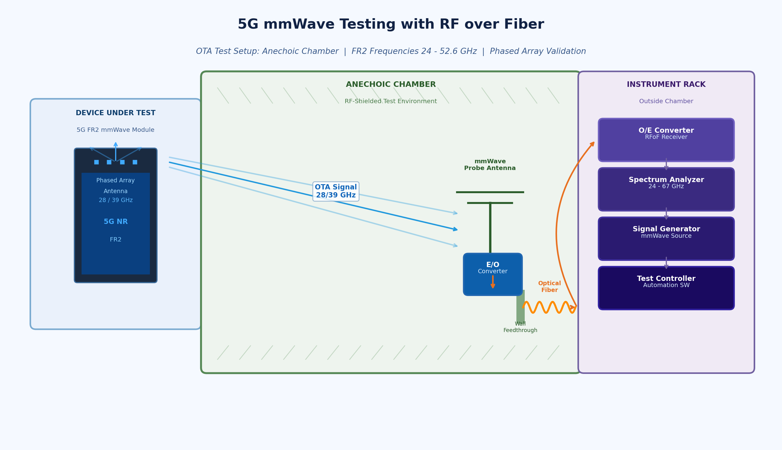
Anechoic Chambers and Remote Antenna Applications
One of the most direct 5G test applications for RFoF is the anechoic chamber setup. In this configuration, the test antenna (probe) is inside the shielded chamber, while the signal generator and analyzer are in the equipment rack outside. Connecting these requires passing the mmWave signal through the chamber wall – a location where coaxial feedthroughs introduce insertion loss, potential leakage, and EMI ingress.
RFOptic offers specific solutions for anechoic chamber applications, recognizing that this is a core use case in the 5G test environment. The optical fiber feedthrough eliminates the shield integrity problem and allows the full mmWave bandwidth to be transported without the frequency-dependent losses of coaxial alternatives.
Preparing for 6G: The Frequency Frontier
While 5G mmWave deployments are still in early phases in many markets, research and pre-standardization work on 6G has already begun at frequencies above 100 GHz – the D-band (110–170 GHz) and beyond. Test infrastructure being deployed today for 5G FR2 will increasingly need to serve as the foundation for 6G research environments.
Choosing RFoF solutions with frequency coverage well beyond the immediate 5G FR2 requirement provides a degree of future-proofing for test facilities. RFOptic’s product family, which extends to 67 GHz in its standard off-the-shelf range, positions test labs to expand measurement capability as 6G frequencies become relevant for device and system characterization.
Engineers specifying rf over fiber modules for 5G test infrastructure are therefore making a technology investment with a long useful life – particularly when the solution comes from a vendor with demonstrated capability well above the minimum required frequency and with a track record of supporting customized configurations.
Conclusion
The shift to 5G FR2 mmWave testing has fundamentally changed what test and measurement infrastructure must deliver. Signal transport between antennas and instruments across the 24–40 GHz range demands low loss, phase stability, EMI immunity, and scalability that coaxial cable cannot reliably provide. RF over fiber has become the standard solution for forward-thinking 5G test labs, and its role will only grow as the industry progresses toward 6G research frequencies.
For test engineers and lab managers evaluating their signal transport architecture, the key criteria are frequency coverage, dynamic range, phase consistency, and the availability of system-level support. Purpose-built RFoF solutions from experienced high-frequency vendors offer the complete package for today’s 5G test challenges and tomorrow’s 6G requirements.
Business Solutions
RPA Security Citizen Developer Governance: The Automation Risk Nobody Is Talking About
Summary: Robotic Process Automation (RPA) has become a cornerstone of enterprise digital transformation, enabling organizations to automate repetitive tasks at scale and free human workers for higher-value activities. But the widespread deployment of RPA bots – increasingly built by non-technical citizen developers rather than professional developers – has created a largely invisible security risk. From over-privileged bot credentials to unmonitored data flows and abandoned automations, the RPA attack surface is growing faster than most security programs can track. This article explores the key security risks in enterprise RPA environments, how citizen developer governance is evolving, and how purpose-built platforms are closing the gap.
The RPA Revolution and Its Security Shadow
Robotic Process Automation – the use of software bots to mimic human interactions with applications and automate repetitive business processes – has become one of the defining technologies of enterprise digital transformation over the past decade. From processing invoices and onboarding employees to reconciling financial data and managing IT service tickets, RPA bots now operate at the heart of critical business processes across virtually every industry.
The market for RPA has grown dramatically, with platforms like UiPath, Automation Anywhere, and Blue Prism embedding themselves deeply into enterprise technology stacks. More recently, low-code RPA capabilities have been integrated directly into broader no-code platforms, with Microsoft’s Power Automate and Salesforce’s Flow Builder enabling any business user to create automated workflows without dedicated RPA tools or expertise.
This democratization of automation has delivered genuine value. Organizations have eliminated backlogs, reduced error rates, accelerated processing times, and redeployed human talent to work that requires judgment and creativity. But the same forces that have made RPA so powerful have also created a security problem that most enterprises have been slow to recognize and even slower to address.
Why RPA Creates a Distinct Security Risk Profile
RPA bots occupy an unusual position in the enterprise security landscape. They are software – and therefore subject to all the vulnerability risks of any enterprise application. But they are also trusted actors within enterprise systems: they log in to applications, access databases, execute transactions, and handle sensitive data with credentials that are often highly privileged.
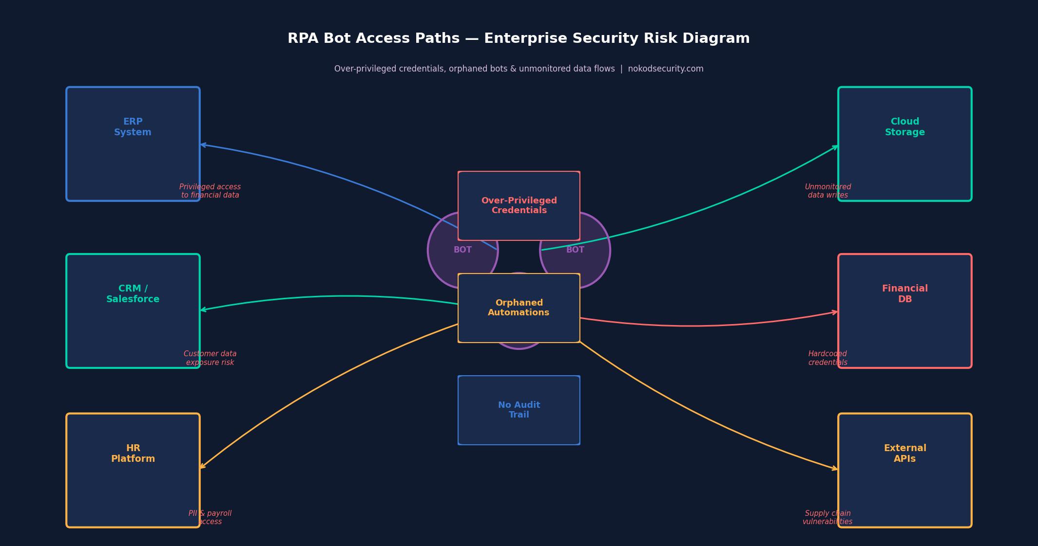
This combination – software with the access rights of a trusted human user – creates a security risk profile that is distinct from both traditional applications and from the human users whose actions they automate. Key risks include:
- Privileged credential exposure: RPA bots require credentials to access the systems they automate. These credentials are frequently stored insecurely – embedded in bot scripts, stored in configuration files, or shared across multiple bots – creating a persistent exposure risk that is difficult to audit and remediate.
- Principle of least privilege violations: Bots are often granted broad access to make the automation easier to build. The result is bots running with far more privilege than their function requires – a violation of basic security hygiene that creates significant blast radius if a bot is compromised or misbehaves.
- Orphaned automations: When the employee who built or managed a bot moves on, the bot typically continues running. Orphaned bots – operating under accounts or credentials that no one is actively managing – represent a persistent, unmonitored risk.
- Injection vulnerabilities: Bots that process unstructured inputs – such as email content, document text, or form submissions – can be vulnerable to injection attacks that cause them to behave in unintended ways.
- Audit trail gaps: Traditional security monitoring is designed to track human user activity. Automated bot activity may not be captured in the same audit logs, creating blind spots in incident investigation and compliance reporting.
- Supply chain risks: Bots that integrate with external systems, APIs, or third-party services introduce supply chain dependencies that may carry their own security vulnerabilities.
The Citizen Developer Dimension
The security challenges of RPA are significantly amplified by the shift toward citizen development – the phenomenon of non-technical business users building automations and bots themselves, outside the formal software development process.
Citizen developers are not security professionals. They are operations managers, finance analysts, HR coordinators, and customer service leads who have learned to use RPA tools to solve their own workflow problems. They are motivated by efficiency, not security. They make decisions about credential storage, access permissions, and data handling based on what makes the automation work, not what makes it secure.
The result is a long tail of citizen-built automations that collectively represent a significant and largely unmanaged attack surface. A single large enterprise may have hundreds or thousands of these automations running across its environment, most of them unknown to the security team, many of them carrying credentials with more access than they need, and some of them no longer actively maintained by anyone.
Research on enterprise citizen development and its governance implications is well-documented. The IEEE Computer Society has published extensively on the governance challenges that arise when software development is democratized beyond professional developers.
How the Market Is Addressing RPA Security
The RPA security market is still maturing. Platform vendors have introduced native security features – UiPath, for example, offers credential management through its Orchestrator platform, and Automation Anywhere has built governance controls into its Cloud platform. These native features are valuable but have meaningful limitations: they are platform-specific, they require significant configuration to be effective, and they do not address the growing volume of RPA capabilities embedded in broader no-code platforms like Power Automate.
The broader security industry has begun to develop dedicated solutions for the automation security problem. Privileged Access Management (PAM) vendors have added bot identity capabilities. SIEM platforms have created analytics rules for detecting anomalous bot behavior. Identity governance tools have extended their coverage to service accounts used by RPA systems.
But none of these approaches addresses the fundamental challenge of governing citizen-built automations across heterogeneous platforms with a unified view, continuous monitoring, and actionable remediation guidance.
Nokod Security: Enterprise-Grade Governance for Automation Security
Nokod Security’s approach to automation security is built on the recognition that the RPA problem cannot be solved platform by platform or control by control. What enterprises need is comprehensive visibility across all their automation assets – regardless of which platform they were built on – combined with continuous security analysis and practical remediation pathways.
Nokod supports UiPath as part of its multi-platform coverage, automatically discovering and mapping automations, analyzing them for security risks, and surfacing findings with the context security teams need to understand and prioritize what they are looking at. The platform identifies the specific risk patterns that characterize enterprise RPA environments: over-privileged credentials, injection vulnerabilities, orphaned automations, insecure data handling, and unsanctioned external integrations.
A critical aspect of Nokod’s approach is its recognition that the security team is not the only actor who needs to take action. Many of the remediations for common RPA security findings need to be carried out by the citizen developers or business owners who built the automations. Nokod is designed to enable this: security findings are surfaced with clear, actionable guidance that business users can understand and act on, and where possible, one-click remediation options eliminate the need for developer expertise.
Building a Citizen Developer Governance Framework
Organizations that want to address the security risks of citizen development at scale need more than tooling alone – they need a governance framework that defines how citizen developers are expected to operate, what guardrails are in place, and how security oversight is maintained without killing the agility that makes citizen development valuable.
Key components of an effective citizen developer governance framework include:
- Inventory and discovery: You cannot govern what you cannot see. Continuous, automated discovery of all citizen-built assets is the foundation of any governance program.
- Risk classification: Not all citizen-built automations carry equal risk. A framework for rapidly classifying automations by risk level – based on data sensitivity, external exposure, and privilege level – enables proportionate oversight.
- Security standards: Clear, practical security standards for citizen developers – covering credential management, data handling, testing, and documentation – must be communicated in terms that non-technical builders can understand and follow.
- Ownership and lifecycle management: Every automation should have a designated owner, and governance processes should trigger reviews when owners change roles or leave the organization.
- Continuous monitoring: Governance cannot be a one-time audit. Continuous monitoring for new assets, configuration changes, and behavioral anomalies is essential.
Conclusion
The automation revolution driven by RPA and citizen development has delivered real value – and it is not going away. Enterprises will continue to expand their automation footprint, and the volume of citizen-built automations will continue to grow. The question is not whether to embrace this trend, but how to do so without accepting a security risk that is invisible, unmanaged, and growing.
Effective citizen developer governance requires acknowledging that the people building these automations are not security experts – and building programs and platforms that meet them where they are. Nokod Security’s approach, which combines deep AppSec expertise with practical tooling designed for both security professionals and business users, represents a model for how enterprises can have both the speed of citizen development and the security governance that responsible enterprise operations require.
The Rise of System-in-Package (SiP): How Advanced IC Packaging Is Redefining Electronics Miniaturization
Wire Bonding vs. Flip Chip: Navigating the Evolving World of IC Interconnect Technology
Optical Delay Lines: The Precision Solution Reshaping Radar and Altimeter Testing

-
Business Solutions2 years ago
Understanding A2P Messaging and the Bulk SMS Business Landscape
-

 Business Solutions2 years ago
The Power of Smarts SMS and Single Platform Chat Messaging
-
 Automotive3 years ago
DSRC vs. CV2X: A Comprehensive Comparison of V2X Communication Technologies
-

 Business Solutions2 years ago
Exploring OTP Smart Features in Smart Messaging Services
-

 Business Solutions2 years ago
Live Video Broadcasting with Bonded Transmission Technology
-

 Business Solutions10 months ago
The Future of Healthcare SMS and RCS Messaging
-

 Business Solutions2 years ago
2-Way Texting Solutions from Company Message Services
-

 Business Solutions2 years ago
Communication with Analog to Fiber Converters & RF Link Budgets