Business Solutions
Optical Delay Lines: The Precision Solution Reshaping Radar and Altimeter Testing
Summary: Radar and altimeter systems must be rigorously tested and calibrated before deploymen-but transmitting live RF energy to simulate target returns is impractical, hazardous, and often impossible in a laboratory or depot environment. This article explains how optical delay lines (ODLs) solve this fundamental challenge, how they work, why fiber-based delay lines outperform electronic alternatives, and how RFOptic’s specialized ODL solutions support radar and altimeter testing programs across defense and aviation markets.
Radar and altimeter testing is one of the most technically demanding areas in defense electronics validation. Systems must be verified to perform accurately across a range of simulated target distances, velocities, and environments-yet doing so by physically placing reflecting targets at the required distances is seldom feasible. The solution lies in optical delay lines, a technology that uses the fixed propagation speed of light in optical fiber to introduce precisely controlled time delays into an RF signal, simulating the time-of-flight of a radar return at a specified range.

The Testing Problem: Why You Cannot Simply Transmit to a Real Target
A radar system determines the range of a target by measuring the round-trip time of a transmitted pulse. An altimeter determines altitude by measuring the time for the transmitted signal to reflect off the ground and return. In both cases, the fundamental measurement is time-of-flight -and testing this measurement requires introducing a known, accurate delay between the transmitted signal and the simulated return.
In field testing, this can be done by physically placing a reference reflector at a known distance. But field testing is expensive, weather-dependent, logistically complex, and often impossible for airborne altimeters (which would require flight testing to validate each range point) or for classified radar systems that cannot be operated in environments where frequency emissions are monitored or regulated. Depot-level maintenance and factory acceptance testing require a bench solution.
Electronic delay lines-switched networks of lumped inductors and capacitors, or surface acoustic wave (SAW) devices-have historically been used for this purpose. But they carry significant limitations: limited frequency range, high insertion loss, temperature-dependent performance, and the inability to cover the multi-microsecond delays needed to simulate distant targets without cascading multiple stages and accumulating noise and distortion.
How an Optical Delay Line Works
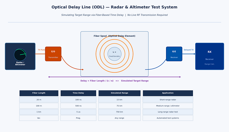
An optical delay line converts the RF signal to be delayed into an optical signal using an electro-optic modulator or laser diode, routes that optical signal through a calibrated length of single-mode optical fiber, then reconverts it back to an RF signal at the output using a photodetector. Since light travels through fiber at approximately 2×1⁰⁸ meters per second (about two-thirds of the speed of light in vacuum), a specific fiber length produces a very precise and stable delay.
For example, approximately 100 meters of fiber produces a delay of around 500 nanoseconds-equivalent to a radar range of approximately 75 kilometers in a monostatic radar configuration. Variable delay lengths can be achieved through switched fiber spools, allowing test equipment to simulate targets at multiple programmable ranges without moving any physical hardware.
The key performance advantages of fiber-based delay lines compared to electronic alternatives are:
• Extremely low loss: optical fiber introduces negligible signal loss per unit length compared to coaxial cable or electronic delay elements at microwave frequencies.
• Frequency independence: the delay is determined purely by the fiber length, not the frequency of the signal. The same ODL works equally well at 1 GHz and at 40 GHz, making it suitable for multi-band radar and wideband altimeter testing.
• Excellent phase stability: fiber delay is not affected by electromagnetic interference and shows very low thermal drift compared to electronic delay networks.
• Scalability: very long delays (microseconds to tens of microseconds) equivalent to hundreds or thousands of kilometers of range-are achievable simply by using more fiber, without cascading lossy electronic stages.
• Electrical isolation: optical fiber passes no DC current and provides complete galvanic isolation between the input and output RF ports, eliminating common-ground interference paths in complex test setups.
Variable and Programmable Optical Delay Lines
The most operationally useful ODL systems offer variable or programmable delay-the ability to switch between multiple discrete delay values to simulate different target ranges. This is achieved through optical switching networks that connect the RF signal to different fiber spools of different lengths, or through continuous variable delay mechanisms using motorized fiber stretchers or optical path length adjustment.
Programmable delay lines are essential for acceptance testing of radar systems that must perform across the full specified range envelope. Rather than resetting physical hardware for each range point, the test engineer selects the desired delay from the ODL’s control interface, and the system switches to the appropriate fiber path within milliseconds. For automated production test environments, this enables rapid, software-controlled multi-point range calibration.
According to the IEEE Transactions on Microwave Theory and Techniques, optical delay line technology has advanced considerably with the integration of programmable switching and temperature compensation, making modern ODL systems suitable for demanding calibration environments where measurement uncertainty must be minimized.
Altimeter Testing: A Specialized Requirement
Radio altimeters-used in commercial aviation, military aircraft, and UAVs to measure height above terrain-are safety-critical systems with stringent testing requirements. Regulatory bodies including the FAA and EASA require verification of altimeter accuracy across the full operating altitude range, typically from near-zero to several thousand feet. Testing each altitude point requires introducing the corresponding time delay between the transmitted altimeter signal and the simulated ground return.
Modern radar altimeters typically operate in the 4.2–4.4 GHz frequency band, though next-generation systems and those for unmanned platforms span wider ranges. Key testing parameters include:
• Absolute accuracy: the altimeter must measure altitude to within a defined tolerance across the full range.
• Response time: the altimeter must update its reading within a specified latency when altitude changes rapidly-important for terrain-following and automatic landing systems.
• Interference immunity: with 5G networks now deployed in the 3.7–4.2 GHz C-band in many countries, regulatory concerns about altimeter interference have made test coverage of adjacent-band interference scenarios a new requirement.
An optical delay line test system for altimeter applications must cover the altimeter’s full altitude range (typically equivalent to delays from a few to several hundred nanoseconds), handle the altimeter’s specific frequency band, and provide calibrated, repeatable delay values. For aircraft integration testing, the system must also operate reliably in the electromagnetic environment of an avionics test bench.
RFOptic’s Optical Delay Line Solutions
RFOptic offers customized low and high frequency optical delay line solutions for testing and calibrating radar and altimeter systems. The company’s ODL product line is described as one of its core competencies, offering both standard and application-specific configurations.
RFOptic provides both fixed and programmable delay configurations, with the following key characteristics as described on their platform:
• Coverage from low frequency through high-frequency microwave and mmWave bands, supporting both current-generation radar and altimeter systems and next-generation wideband applications.
• Customized ODL systems developed to customer specifications, including integration with specific test equipment interfaces and control software.
• Online request-for-quote tool for customized ODL and altimeter ODL systems, supporting design consultation from the earliest project stage.
• Subsystem integration: RFOptic’s ODLs can be integrated into complete radar and altimeter test subsystems, combining the delay function with signal conditioning, switching, and management interfaces.
RFOptic’s value proposition emphasizes that in the pre-sales stage, the company builds solutions tailored to customer needs, including simulations that predict link behavior-particularly important for ODL systems where target delay accuracy and dynamic range must be verified analytically before hardware is built.
Emerging Applications: UAV Altimeters and Radar Testing
The rapid growth of unmanned aerial systems (UAS/UAV) has created a new generation of altimeter testing requirements. Drone altimeters are smaller, lighter, and often operate in different frequency bands than traditional aviation altimeters. They must be validated for low-altitude terrain-following, precision landing approaches, and operation in spectrum-contested environments. The same fundamental principle applies: fiber-based optical delay lines provide the most accurate and flexible platform for simulating the required altitude ranges in a laboratory setting.
For those evaluating radar testing solutions, the combination of programmable delay ranges, wide frequency coverage, and low noise floor that optical delay lines provide makes them the reference tool of choice across military radar, commercial aviation, and UAV development programs.
Conclusion
Optical delay lines represent a technically elegant solution to one of the oldest problems in radar and altimeter development: how to test time-of-flight accuracy without deploying hardware into the field. By leveraging the fixed and stable propagation speed of light in optical fiber, ODL systems deliver highly accurate, repeatable, and frequency-independent delay values that electronic alternatives cannot match at microwave and mmWave frequencies.
For radar system developers, avionics test labs, and depot maintenance facilities, investing in optical delay line test equipment-particularly programmable systems capable of simulating multiple range points-is a practical step that reduces test time, improves calibration accuracy, and future-proofs the test infrastructure for next-generation wideband radar and altimeter systems.