


Business Solutions
How Fiber Optic Receivers Enhance RF Conversions

Looking forward, integrated photonics may allow an entire conversion chain to fit onto a single chip. Such a design could drastically reduce power consumption and form factor while boosting performance. Fiber optic receivers, in tandem with these specialized chips, might soon handle multiple frequency bands concurrently, switching dynamically based on network load or environmental conditions. This adaptability could pave the way for agile, reconfigurable networks that seamlessly scale to match global data traffic demands.
Organizations that keep an eye on these developments stand to gain a competitive edge, whether in telecom, defense, or broadcast. By staying current with the latest converter rf breakthroughs and the next generation of fiber optic receivers, businesses can future-proof their infrastructure against rising bandwidth requirements and the relentless march of innovation. The synergy between these technologies looks set to continue reshaping communications, offering a blueprint for systems that are more efficient, secure, and capable than ever.
Introduction to Converter RF and Fiber Optic Receivers
Converter rf equipment often forms the backbone of systems requiring reliable frequency translation. In such setups, signals may need to be converted (up or down) to facilitate specific tasks. Meanwhile, fiber optic receivers tackle the challenging realm of transporting these signals across long distances with minimal attenuation. One of the biggest reasons these technologies fit well together is their capacity to handle higher frequencies in a cleaner, more secure way than older, coax-based solutions. When signals move from the radio frequency domain into the optical domain, they can traverse extensive networks without succumbing to common pitfalls like electromagnetic interference.
Organizations spanning telecommunications, aerospace, and research labs benefit from combining converter rf and fiber optic receivers. The synergy between these devices allows them to push data faster and farther, all while retaining quality. Over time, as systems scale up or adapt to new standards, integrating new frequencies becomes simpler. This approach has proven invaluable in everything from satellite communications to advanced sensor applications, where clarity and fidelity are paramount.
Understanding RF Conversion Fundamentals
Radio frequency conversion plays a critical role in modern communication designs. At its simplest level, an RF signal can be shifted upward (upconversion) or downward (downconversion) to match the requirements of a particular system. By altering the frequency range, these signals become more manageable, either because they avoid interference in specific bands or because certain hardware performs more effectively at certain frequencies. While it seems straightforward, the underlying technology is quite intricate, relying on mixers, local oscillators, amplifiers, and filters to ensure the final signal remains clean and stable.
Two paragraphs might not suffice to unravel every element of frequency conversion, but they highlight the complexity and importance of these steps. Whether dealing with microwave links or satellite feeds, the converter rf stage must handle even the slightest changes in amplitude or phase. If not carefully managed, distortion creeps into the system, causing data loss or degraded communication. This is one reason hardware selection and design criteria demand precision. Shoddy mixers or poorly implemented oscillators often lead to cascading issues downstream.
The Core Role of Fiber Optic Receivers
Fiber optic receivers bridge the gap between optical signals and the electrical domain. Unlike copper cables, optical fibers are immune to electromagnetic interference, allowing them to maintain signal integrity over significant distances. As frequency demands intensify—particularly when systems rely on converter rf stages to move signals around the spectrum—fiber comes to the rescue by preserving each bit of information as pulses of light. Traditional copper solutions can’t offer the same low-loss, high-bandwidth advantages, especially over many kilometers.
One reason these receivers excel is their sensitive photodiodes that convert incoming light back into an electrical current. With proper calibration, they can detect minuscule variations in optical intensity, ensuring the original RF data remains faithful to its source. As high-frequency deployments grow more prevalent in defense, broadcasting, and scientific research, fiber optic receivers become vital. They align perfectly with upconverted or downconverted signals, mitigating problems like crosstalk or signal degradation. In essence, they’re the missing puzzle piece that ensures data transitions smoothly from light to radio frequency and back again.
Minimizing Noise and Distortion
Keeping noise and distortion at bay is paramount for any RF-based setup. When signals undergo conversion, they risk unwanted interference introduced by mixing processes, local oscillator leakage, or suboptimal filtering. This contamination can worsen if the system relies on copper-based transmission lines for intermediate stages, as electromagnetic fields or thermal noise may further degrade signal integrity. The combined effect is often observed as a lowered signal-to-noise ratio, making it harder to decode or transmit data reliably.
Engineers tackle these hurdles in a variety of ways. They might shield sensitive circuitry or incorporate advanced filtering that hones in on the desired frequency band. Sufficient gain control also matters; too much amplification might saturate the mixer and add nonlinear distortion. Meanwhile, too little amplification can render the signal too weak once it hits the next stage. Incorporating fiber optic receivers adds another layer of protection. Because optical media does not conduct electricity, it eliminates pathways for external noise. Signal clarity remains high, even in environments rich in high-power electronics or radio emissions.
One of the lesser-discussed elements is temperature stability. Components like mixers and oscillators can drift slightly in frequency with changes in ambient conditions. Over time, small drifts accumulate and shift the signal away from its target band. Engineers often add temperature-compensating circuits or place converters in controlled enclosures to preserve alignment. By adopting such strategies, they ensure the system stays firmly locked on the desired channel, minimizing distortion from environmental factors.
Designing a Reliable Converter RF Setup
Crafting a robust architecture around converter rf starts with identifying clear goals: required frequency range, power levels, and data throughput. Once those are set, designers look at link budgets, choosing appropriate amplifiers and filters to ensure minimal loss. It helps to think of the signal path as a chain where each link must be as strong as the next. A single weak or mismatched component can drag down overall performance, causing errors that ripple through the entire communication system.
Many designers also incorporate fallback or redundancy. For mission-critical applications—like emergency communication networks—having multiple converter rf paths ensures that the system stays operational even if one line fails. This approach might involve parallel modules running slightly different frequencies or backup fiber routes that circumvent the primary link. The aim is always to avoid single points of failure. Additionally, adopting fiber optic receivers acts as a protective measure. Their inherent immunity to electromagnetic interference and ability to handle high data rates with low attenuation improves the reliability of each link in the chain.
Comparing Analog vs. Digital RF Conversion
When moving signals into different frequency bands, you can choose analog or digital methods. Analog conversion preserves the waveform’s continuous nature, which can be valuable when ultra-low latency or high fidelity is the priority. However, it may be more susceptible to noise and may need precisely matched mixers, filters, and oscillators to deliver consistent results. In contrast, digital conversion processes the waveform as bits, potentially enabling sophisticated error correction and compression. But digital systems may introduce additional latency and can demand higher power or more complex equipment.
Neither approach is universally better. The choice boils down to application requirements. Satellite operators or radio astronomers might lean toward analog to capture subtle signal variations. Streaming platforms or data centers handling massive volumes might opt for digital to leverage advanced encoding or encryption. In both cases, fiber optic receivers support the final stages, transmitting the signal—be it analog or digital—across optical fibers with minimal loss. That synergy points to why converter rf solutions must be carefully matched to the overall design, factoring in cost, performance, and future scalability.
Many engineers find themselves in hybrid scenarios. Certain parts of a system run analog conversions, while others incorporate digital front-ends to handle tasks like filtering or signal conditioning. While it can add complexity, a hybrid design can maximize performance in specific regions of the signal path. Ultimately, both analog and digital revolve around the same objective: deliver the highest-quality data from point A to point B with minimal noise or distortion.
Selecting the Right Fiber Optic Receivers
Choosing suitable fiber optic receivers involves evaluating criteria like sensitivity, dynamic range, and operational wavelength. Sensitivity indicates how weak a signal the receiver can interpret accurately, which becomes critical when spanning large distances or working at higher frequencies. Dynamic range reveals how well the receiver handles both faint and strong signals without distorting either one. Additionally, different fibers use distinct wavelength windows—commonly 1310 nm or 1550 nm—so matching the receiver’s wavelength capabilities to the system is essential.
Environmental conditions also play a part. Receivers must handle temperature variations, humidity, and, in some cases, vibrations from heavy machinery. Industrial or ruggedized models include sealed enclosures and reinforced connectors to cope with extreme settings. Meanwhile, in controlled environments like data centers, simpler enclosures might suffice, focusing more on raw performance metrics. Investing in high-quality receivers can yield dividends later, as subpar components often introduce incremental losses or require frequent maintenance.
Cost is another consideration. Fiber optic receivers span a wide range of price points based on their complexity and intended frequency range. Cheaper units might work well for short distances or simpler topologies, but advanced converter rf setups often justify premium hardware to ensure consistent, reliable transmission. Adopting a forward-looking strategy, where a slightly more capable receiver can handle upcoming expansions, prevents frequent hardware swaps down the road.
Handling High-Frequency Signal Loss
Operating at higher radio frequencies tends to amplify the impact of signal loss. Resistive losses, dielectric absorption, and scattering effects all become more pronounced. As frequencies climb, coax lines can quickly diminish signal power unless accompanied by repeaters or high-gain amplifiers. It’s here that combining converter rf with fiber optic receivers presents a compelling solution. By converting signals into optical form, one can largely circumvent the crippling losses inherent in copper lines at high frequencies.
In some sectors, like 5G infrastructure or military communication, signals in the millimeter-wave region (above tens of GHz) face extreme attenuation. Even short runs can cause noticeable degradation. A robust converter stage followed by fiber transmission can reduce or eliminate such problems. Additionally, splicing modern low-loss fiber cables has become fairly routine, making it simpler to extend or modify networks without incurring heavy signal penalties.
Engineers must also watch for mechanical factors. Kinks or bends in the fiber can lead to partial reflections of the light beam, lessening the net power at the receiver. Carefully planned cable trays and protection against crushing forces ensure the optical path remains consistent. While fiber is somewhat fragile, it repays careful handling with stable, long-term performance superior to nearly any coax alternative in high-frequency contexts.
Integrating Converter RF with Existing Systems
Merging advanced converter rf equipment into current infrastructure can be tricky. Legacy systems might rely on outdated interfaces, or they could be locked into certain frequencies. Determining how best to align new modules requires careful planning. You might need adapters or specialized couplers to bridge older coaxial ports with fresh optical lines. Another factor is the power supply, especially if older racks can’t deliver the voltage or current needed for advanced converter units.
Some operators address these challenges by phasing in new hardware. They partition sections of the network, upgrading them incrementally. This approach reduces downtime while still maintaining partial functionality. Over time, the entire system transitions away from older technology and reaps the benefits of fiber optic receivers and modern conversion methods.
Documentation becomes critical. Clear wiring diagrams, frequency allocations, and device configurations help troubleshoot any issues that arise after integration. Large facilities often keep a thorough inventory of components, so technicians can identify or replace any part if something goes awry. By incorporating modern converter rf modules gradually, organizations minimize risk while progressively elevating system performance.
Testing and Calibrating RF Networks
Regular testing and calibration ensure your converter rf network operates as intended. Technicians typically measure power levels, frequency accuracy, noise figures, and other performance metrics. Spectral analyzers may highlight unwanted spurious signals, local oscillator leakage, or mixing products. Identifying these anomalies early can prevent disruptions or wasted bandwidth. Some setups also rely on reference signals to keep local oscillators locked to a precise standard, ensuring minimal drift over time.
Calibrating fiber optic receivers is equally crucial. Even small variations in a photodiode’s gain can lead to discrepancies in output power, complicating data processing. Organizations often schedule calibration intervals, especially where continuous operation is a must, such as in broadcasting or defense communications. With advanced digital monitoring, systems can send alerts if performance dips below a set threshold, prompting preventive maintenance before an outright failure occurs.
Beyond the hardware, software alignment matters. Configurations for modulation schemes, error correction, and bandwidth settings must harmonize between transmitters and receivers. If parameters become mismatched—perhaps during a firmware update—communication can degrade rapidly. Testing is the final safeguard that ensures these elements align, supporting consistent, high-quality links.
Maintenance Tips for Long-Term Performance
Prolonged uptime hinges on adopting preventive measures. For instance, fiber connections benefit from routine cleaning of connectors to remove dust or small particles that might scatter light. Periodic re-checking alignment angles can keep signals optimized. Because converter rf modules include sensitive mixers and oscillators, verifying temperature control mechanisms should also be part of regular maintenance schedules.
Many professionals log performance metrics over time to detect trends that suggest hardware fatigue or environmental influences. If a power amplifier consistently overheats in summer months, it might point to ventilation issues in the equipment rack. Similarly, fluctuations in local oscillator stability could trace back to a failing internal voltage regulator. Addressing these insights proactively mitigates system-wide breakdowns.
In some high-availability networks, remote monitoring software plays a key role. Automated alerts draw attention to anomalies—like sudden drops in optical power or shifts in local oscillator frequency. These timely notifications let engineers intervene early. Ultimately, a blend of hardware upkeep, environmental management, and real-time analytics ensures converter rf and fiber optic receivers remain in prime working condition.

Introduction
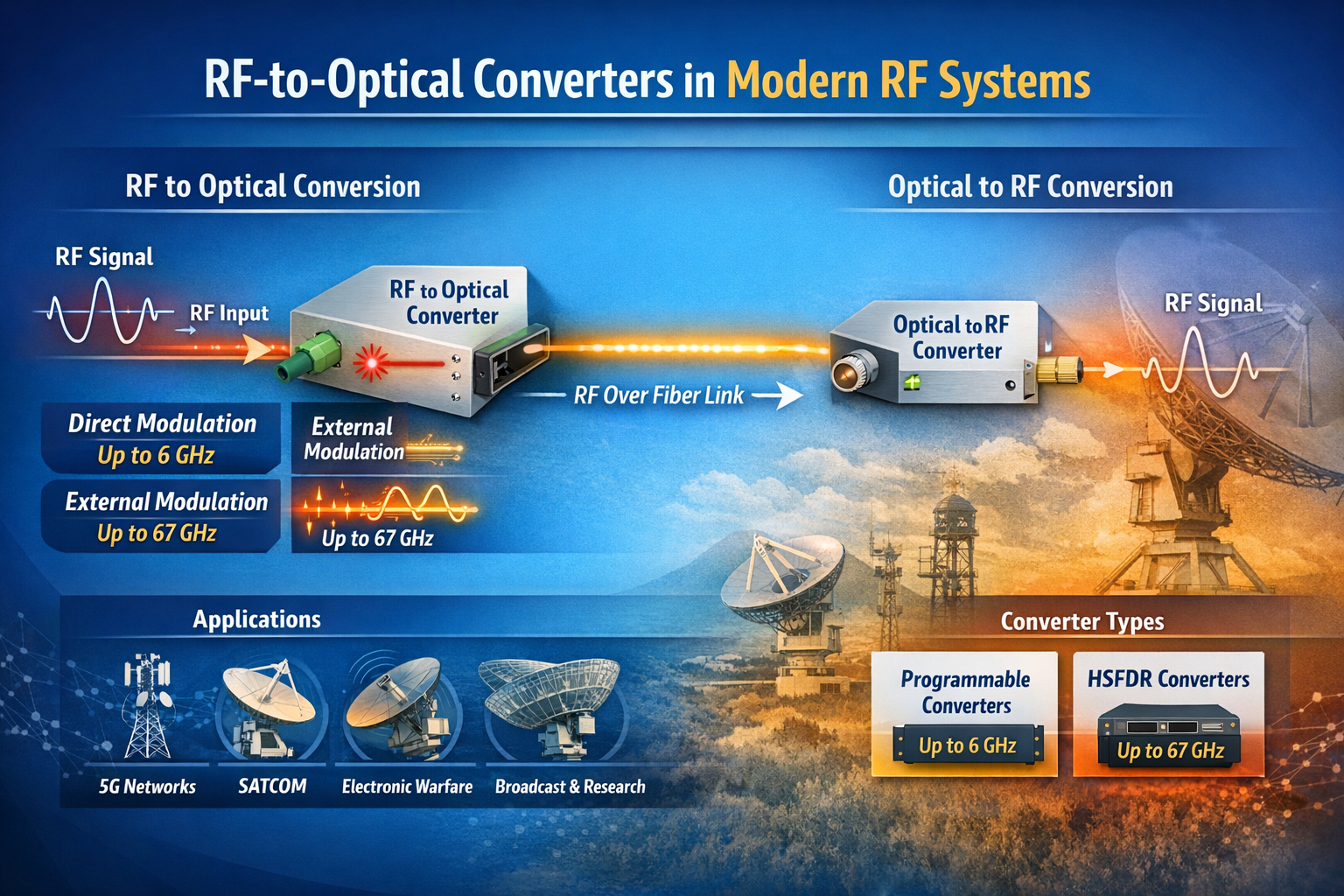
The term “RF converter” encompasses a broad category of devices that change the form or frequency of an RF signal. In traditional RF engineering, an RF converter might refer to a frequency converter (mixer + local oscillator) that translates a signal from one frequency band to another. In the context of RF over fiber technology — a rapidly growing field — an RF converter specifically refers to a module that converts between the RF electrical domain and the optical domain.
This article focuses on RF-to-optical converters (and their optical-to-RF counterparts), the core building block of any RF over fiber (RFoF) system. We explain how they work, what parameters differentiate high-performance converters from commodity devices, and where they are used across today’s most demanding RF applications.
What Is an RF-to-Optical Converter?
An RF-to-optical converter — commonly called an RFoF transmitter module or RFoF Tx — is a device that accepts an RF electrical signal at its input and produces a modulated optical signal at its output. The conversion is achieved by using the RF signal to modulate the intensity (or phase) of a laser light source:
- Direct Modulation: The RF signal directly drives the bias current of a laser diode, modulating its output power. This approach is simpler and more compact, but has bandwidth limitations (typically up to 6–8 GHz) and higher relative intensity noise (RIN).
- External Modulation (Electro-Optic Modulation): A continuous-wave (CW) laser feeds a Mach-Zehnder modulator (MZM) or other electro-optic device, which modulates the optical signal using the RF input. This approach supports much higher frequencies (up to 40 GHz, 67 GHz, and beyond) and achieves superior linearity and dynamic range.
The complementary device — the optical-to-RF converter, or RFoF receiver (Rx) — is a photodetector module that converts the incoming optical signal back into an RF electrical signal. Together, an Tx and Rx module form a complete RFoF link.
RF Converter Families: Programmable vs. HSFDR
In the RFoF market, RF converters are typically divided into two performance tiers:
Programmable RF Converters
Programmable RFoF converters use direct modulation laser technology and cover bandwidths from 1 MHz up to 2.5 GHz, 3 GHz, 4 GHz, 6 GHz, or 8 GHz. They are configurable via software (such as a USB-connected configuration tool) for gain, bias, and diagnostic parameters. RFOptic’s programmable RF converter family covers these bands and is widely used in GPS distribution, cellular DAS, public safety networks, and broadcast applications.
Key characteristics of programmable RF converters:
- Direct modulation technology — compact and cost-effective
- Configurable gain and bias via USB and software
- Suitable for bandwidths up to 6–8 GHz
- Diagnostic RF test of Tx, Rx, and end-to-end link
- Available in enclosed and OEM module form factors
High SFDR (HSFDR) RF Converters
High Spurious-Free Dynamic Range (HSFDR) RF converters use external electro-optic modulation to achieve superior linearity and frequency coverage. These converters are designed for applications where dynamic range and wideband performance are paramount — electronic warfare, radar, satellite communications, and 5G FR2 millimeter-wave testing.
HSFDR converters from RFOptic cover bandwidths from 100 MHz up to 20 GHz, 40 GHz, and 67 GHz, making them the appropriate choice when the application exceeds the frequency ceiling of direct modulation systems.
Key characteristics of HSFDR RF converters:
- External electro-optic modulation — highest linearity and frequency coverage
- Covers L, S, C, X, Ku, K, Ka, and V bands (up to 67 GHz)
- High SFDR — critical for multi-carrier and wideband signal transport
- Lower noise figure compared to direct modulation equivalents at high frequencies
- Available in benchtop, rack-mount, and OEM configurations
RF Converter Frequency Coverage: Market Comparison
Frequency range is the single most important differentiator between RFoF converter providers. While the mainstream market is well served by converters operating up to 3–6 GHz, the growth of mmWave 5G, Ka-band SATCOM, and broadband EW systems demands converters operating at 18 GHz, 40 GHz, and beyond.
| Max Frequency | Technology | Key Applications | Coverage Tier |
|---|---|---|---|
| Up to 6 GHz | Direct modulation | GPS, DAS, public safety, C-band 5G | Standard |
| Up to 18 GHz | Direct / external modulation | X-band radar, wideband EW, Ku SATCOM | Mid-range |
| Up to 40 GHz | External modulation (EOM) | Ka-band SATCOM, mmWave 5G FR2, EW | High performance |
| Up to 67 GHz | External modulation (EOM) | V-band, EW/SIGINT, mmWave radar | Specialty / high-end |
RFOptic’s standard RF over fiber converter portfolio spans from the 2.5 GHz programmable tier all the way to a 67 GHz HSFDR product, providing a single-vendor solution across this entire frequency range. Details are available at rfoptic.com/standard-rf-over-fiber-links/.
Where Are RF Converters Used?
Cellular and 5G Networks
RF converters form the backbone of distributed antenna systems (DAS) and C-RAN (Cloud Radio Access Network) architectures, transporting RF signals from base stations to remote antenna locations over fiber. With 5G expanding into millimeter-wave (FR2) bands at 24–39 GHz, high-frequency RF converters are increasingly required for this market.
Satellite Communications Ground Stations
SATCOM ground stations use RF converters to transport IF and L-band signals from outdoor antenna equipment to indoor modem racks. High-frequency converters support the full IF range including Ka-band (26.5–40 GHz) and V-band without requiring downconversion — preserving signal fidelity and simplifying the signal chain.
Electronic Warfare and Defense
EW systems transport broadband RF signals from antenna arrays to signal processing hardware using RFoF converters. The key requirements are high SFDR, low noise figure, and wide frequency coverage. RFOptic’s EW & Radar solutions address these requirements with HSFDR converters covering L through V bands.
Test and Measurement
RF over fiber converters are used in antenna measurement ranges, EMC test chambers, and anechoic chambers to transport signals between the antenna under test and the measurement instrumentation. The fiber cable does not perturb the electromagnetic environment of the test chamber, unlike coaxial cable, which can act as an unintentional radiator.
Broadcast and Radio Telescope
Broadcast and scientific radio applications use RFoF converters to transport RF signals over long distances between antennas and processing centers. The low loss and wide bandwidth of fiber make it ideal for very long link distances where coaxial cable attenuation would be prohibitive.
Selecting the Right RF Converter
When choosing an RF converter for a specific application, engineers should evaluate:
- Frequency range: Does the converter cover the full operating band of your application, including any tuning range or harmonic considerations?
- Dynamic range (SFDR): Is the SFDR sufficient for the number of channels and signal levels in your system?
- Noise figure: What is the minimum detectable signal level? Is the converter’s NF compatible with your system noise budget?
- Form factor: Enclosed module, OEM PCB, benchtop, or rack-mount?
- Programmability: Do you need software-configurable gain and bias, or is a fixed design sufficient?
- Optical power budget: What fiber span and connector count will the link need to support?
- Remote management: Is SNMP, REST API, or HTML-based remote monitoring required?
For a full overview of RF over fiber converter products and applications, visit rfoptic.com.
Frequently Asked Questions (FAQ)
What is an RF converter in the context of RF over fiber?
In RF over fiber systems, an RF converter refers to the transmitter module (Tx) that converts an RF electrical signal into a modulated optical signal, or the receiver module (Rx) that converts the optical signal back to RF. Together, they form a complete RF-to-optical-to-RF conversion link over fiber cable.
What is the difference between a programmable RF converter and an HSFDR converter?
Programmable RF converters use direct modulation laser technology, covering bandwidths up to 6–8 GHz, and are configurable via software for gain and bias settings. HSFDR (High Spurious-Free Dynamic Range) converters use external electro-optic modulation, covering frequencies up to 67 GHz, and are optimized for high linearity and dynamic range in demanding defense, SATCOM, and test & measurement applications.
What frequency range do RF-to-optical converters support?
Standard RFoF converters cover 1 MHz to 6 GHz. High-performance RF converters using external electro-optic modulation, such as RFOptic’s HSFDR product family, support frequencies up to 67 GHz — covering L, S, C, X, Ku, K, Ka, and V bands in a single product line.
Can RF converters support bidirectional RF signals?
Yes. Most RFoF systems support bidirectional operation using wavelength division multiplexing (WDM) to separate the uplink and downlink signals on a single fiber. Some systems use a separate fiber for each direction. The configuration depends on the system’s wavelength plan and the WDM components available.
Where can I find technical datasheets for RF over fiber converters?
RFOptic provides technical specifications and datasheets for its full range of RF converters at rfoptic.com/standard-rf-over-fiber-links/. Specifications include frequency range, link gain, noise figure, SFDR, and optical power budget for each product in the programmable and HSFDR families.
Business Solutions
Drone-UAV RF Communication: The Backbone of Modern Aerial Operations
Drone-UAV RF Communication is revolutionizing the way drones operate, serving as the foundation for reliable, efficient, and innovative aerial systems. From ensuring seamless connectivity to enabling advanced maneuvers, this technology plays a pivotal role in modern drone operations. Its ability to provide consistent and secure communication is what makes it indispensable for both commercial and defense applications.

Unmanned Aerial Vehicles (UAVs), commonly known as drones, have become a pivotal technology across industries such as defense, agriculture, logistics, and surveillance. At the core of a drone’s functionality is its communication system, which enables control, data transfer, and situational awareness. Radio Frequency (RF) communication plays a crucial role in ensuring that UAVs can operate effectively in a variety of environments, with high reliability and low latency. Learn more about DRONE-UAV RF COMMUNICATION.
This article delves into the significance of RF communication in Drone-UAV operations, the challenges it presents, the technologies involved, and how future advancements are shaping the communication systems for UAVs.
The Role of RF Communication in Drone-UAV Operations
RF communication is the medium through which most drones communicate with ground control stations (GCS), onboard systems, and other UAVs in a network. It enables the transmission of various types of data, including:
Control Signals: These are essential for operating the UAV, including commands for takeoff, landing, navigation, and flight adjustments.
Telemetry Data: Real-time data on the UAV’s performance, including altitude, speed, battery level, and sensor readings.
Video and Sensor Data: Drones equipped with cameras or other sensors (such as thermal, LiDAR, or multispectral) require high-bandwidth RF communication to send video feeds or sensor data back to the ground station.
Learn more about Optical Delay Line Solutions.
Payload Data: UAVs used for specific tasks like delivery or surveillance may need to transmit payload-related data, such as GPS coordinates, images, or diagnostic information.
Given the variety of data types and the need for real-time communication, a robust and reliable RF communication system is essential for the successful operation of drones in both civilian and military applications.
RF Communication Technologies for Drone-UAVs
The communication requirements of drones are diverse, necessitating different RF communication technologies and frequency bands. These technologies are designed to address challenges such as range, interference, data rate, and power consumption.
1. Frequency Bands
The RF spectrum is divided into several frequency bands, and each is used for different types of communication in UAV systems. The most commonly used frequency bands for drone communications are:
2.4 GHz: This band is one of the most popular for consumer-grade drones. It offers a good balance of range and data transfer speed, although it is prone to interference from other wireless devices (such as Wi-Fi routers and Bluetooth devices).
5.8 GHz: This band is often used for high-definition video transmission in drones, as it offers higher data rates than 2.4 GHz, but with a slightly shorter range. It’s less crowded than 2.4 GHz and typically experiences less interference.
Sub-1 GHz (e.g., 900 MHz): This frequency is used for long-range communications, as lower frequencies tend to travel farther and penetrate obstacles more effectively. It’s ideal for military drones or those used in remote areas.
L, S, and C Bands: These bands are used in military and commercial UAVs for long-range communication, often for surveillance, reconnaissance, and tactical operations. These frequencies have lower susceptibility to interference and are better suited for higher-power transmissions.
2. Modulation Techniques
The RF communication system in drones uses different modulation techniques to efficiently transmit data. Modulation refers to the method of encoding information onto a carrier wave for transmission. Some common modulation techniques used in UAV RF communication include:
Frequency Modulation (FM): Often used in control signals, FM is simple and efficient, providing clear communication with minimal interference.
Amplitude Modulation (AM): Used for video and lower-bandwidth applications, AM transmits a signal whose amplitude is varied to carry the information.
Phase Shift Keying (PSK) and Quadrature Amplitude Modulation (QAM): These more advanced techniques allow for high data transfer rates, making them ideal for transmitting high-definition video or large sensor datasets.
3. Signal Encoding and Error Correction
To ensure that RF communication remains stable and reliable, especially in noisy or crowded environments, drones use advanced signal encoding and error correction methods. These techniques help to mitigate the impact of signal interference, fading, and packet loss. Common methods include:
Forward Error Correction (FEC): This involves adding redundant data to the so that errors can be detected and corrected at the receiver end.
Diversity Reception: Drones may employ multiple antennas or receivers, allowing them to receive signals from different directions and improve the overall reliability of communication.
Spread Spectrum Techniques: Methods like Frequency Hopping Spread Spectrum (FHSS) or Direct Sequence Spread Spectrum (DSSS) spread the signal over a wider bandwidth, making it more resistant to jamming and interference.
4. Long-Range Communication
For long-range missions, RF communication technology needs to go beyond traditional line-of-sight communication. To achieve this, drones can leverage various technologies:
Satellite Communication (SATCOM): When beyond-visual-line-of-sight (BVLOS) operations are required, drones can use satellite links (via L, S, or Ku-band frequencies) to maintain constant communication with the ground station.
Cellular Networks: 4G LTE and 5G networks are increasingly being used for drone communication, especially in urban environments. 5G, in particular, offers ultra-low latency, high-speed data transfer, and extensive coverage.
Mesh Networking: Some UAVs can form mesh networks where each drone communicates with others in the fleet, extending the range of the communication system and providing redundancy.
Challenges in Drone-UAV RF Communication
While RF communication is essential for UAVs, it presents several challenges that need to be addressed to ensure the reliable and secure operation of drones.
1. Interference and Jamming
One of the biggest threats to RF communication in drones is interference from other electronic systems or intentional jamming. Drones, especially in crowded or military environments, must be capable of avoiding interference from various sources, such as:
Other drones operating on the same frequencies.
Wireless communication systems like Wi-Fi or Bluetooth.
Intentional jamming by adversaries in conflict zones or hostile environments.
To mitigate these issues, drones use frequency hopping, spread spectrum techniques, and advanced error-correction algorithms to make communication more resilient.
2. Limited Range and Power Constraints
The effective range of RF communication in drones is limited by factors such as transmitter power, antenna design, and frequency band characteristics. While UAVs with longer ranges can use lower frequencies like 900 MHz or satellite links, they are often limited by battery life and payload capacity.
The trade-off between range and power consumption is an ongoing challenge. Drones must find a balance between maintaining communication and extending their operational flight times.
3. Security Risks
The RF communication channel is vulnerable to security threats, such as signal interception, spoofing, and hacking. Unauthorized access to the communication link could compromise the integrity of the UAV’s operations or allow malicious actors to take control of the drone.
To secure drone communications, encryption methods like AES (Advanced Encryption Standard) and TLS (Transport Layer Security) are employed, ensuring that only authorized parties can decrypt and interpret the transmitted data.
4. Latency and Data Throughput
For applications that require real-time control and feedback, such as autonomous drones or those used in first-responder scenarios, low-latency communication is crucial. High latency could delay mission-critical decisions, especially in dynamic environments like search and rescue operations or military engagements. Additionally, high-data-throughput applications like video streaming require RF systems with robust bandwidth management.
Future Trends in Drone-UAV RF Communication
As UAV technology continues to advance, so will the communication systems that power them. Key trends in the future of drone RF communication include:
5G and Beyond: The rollout of 5G networks is expected to revolutionize drone communications with ultra-low latency, high bandwidth, and greater network density. This will enable more drones to operate simultaneously in urban environments, enhance remote operation, and facilitate advanced applications such as drone swarming and real-time video streaming.
Artificial Intelligence (AI) for Dynamic Communication: AI-powered algorithms can optimize communication links based on environmental conditions, such as avoiding interference, adjusting frequencies, and ensuring maximum data throughput. AI will also play a role in improving autonomous decision-making for UAVs in communication-heavy operations.
Integration with IoT: Drones are increasingly integrated into the Internet of Things (IoT) ecosystem. As a result, drones will not only communicate with ground control but also with other devices and systems in real-time. This opens new possibilities for industrial applications like smart farming, precision delivery, and environmental monitoring.
RF communication is at the heart of every drone’s operation, whether for military, industrial, or commercial use. As UAV technology continues to evolve, so too must the communication systems that support them. RF communication technologies are enabling drones to perform increasingly complex tasks, from surveillance and reconnaissance to logistics and environmental monitoring.
Despite the challenges posed by interference, range limitations, and security risks, advances in RF technology, coupled with innovations like 5G and AI, promise to take UAV communication systems to new heights—fostering more reliable, secure, and efficient operations across a range of industries.
Business Solutions
OTP Verification at Scale with VoIP Smart Support
Effortlessly manage OTP Verification at scale with VoIP Smart Support. Experience secure, reliable, and efficient solutions designed to meet the demands of growing businesses. Simplify authentication and enhance user trust. Discover how VoIP Smart Support can elevate your verification process today!

Why Secure Access Needs Smarter Infrastructure
Every second, thousands of users worldwide are receiving one-time passwords to log in, confirm a transaction, or recover access to their accounts. But as digital engagement increases, the flaws in conventional delivery systems are becoming impossible to ignore. Delays, failed messages, and spoofed calls are undermining trust. That’s why scaling an OTP verification service now demands more than basic connectivity—it requires intelligent routing, redundancy, and optimization. Enter VoIP smart technology.
VoIP smart systems are transforming how one-time codes are delivered at scale, offering real-time, programmable, and efficient voice-based alternatives that ensure the code always reaches its destination, regardless of region or network barriers.
What Makes an OTP Verification Service Work?
At its core, an OTP verification service revolves around speed, precision, and trust. Users expect their one-time passwords to arrive immediately—usually within a few seconds—regardless of how or where they’re delivered. This is especially crucial in time-sensitive scenarios like banking logins, e-commerce checkouts, or account recovery.
An OTP system typically includes:
- A token generator to create time-limited codes
- A delivery mechanism (SMS, voice, or app)
- A validation module to check the input from the user
- A logic layer to handle retries, timeouts, and fallbacks
While SMS remains the most popular method, it’s no longer the most reliable—especially across regions with telecom restrictions, low infrastructure coverage, or aggressive message filtering. That’s where smarter alternatives like voice-based delivery come in, backed by intelligent VoIP infrastructure.

The Weak Spots in Traditional OTP Delivery
Many companies stick with SMS OTP because it’s familiar. But familiarity doesn’t guarantee performance. In reality, SMS delivery can be disrupted by:
- Carrier-level A2P (application-to-person) message filtering
- Regulatory hurdles like DND lists and local restrictions
- SIM swapping and spoofing attacks
- Latency due to congested telecom gateways
Worse, there’s minimal visibility when something fails. Delivery receipts are inconsistent, and troubleshooting is often reactive. The result? Lost users, failed logins, and poor brand experience.
By integrating VoIP smart solutions into your OTP verification service, you build resilience into the authentication process, especially in regions with high SMS failure rates.
Enter VoIP Smart: More Than Just Internet Calling
VoIP—short for Voice over Internet Protocol—has long been associated with internet-based calling. But VoIP smart takes it a step further by layering in programmable logic, intelligent routing, and real-time performance optimization.
Instead of simply placing a call, a smart VoIP system evaluates the best route, analyzes delivery quality in real time, and adapts on the fly. It can detect if a number is unreachable and retry through an alternate channel or carrier.
This intelligence is exactly what an enterprise-scale OTP verification service needs. It turns voice OTP delivery from a blunt fallback option into a strategic channel—capable of outperforming SMS in reliability and reach.
How VoIP Smart Transforms OTP Voice Delivery
Voice OTP delivery works by placing an automated call to the user and delivering the code through either a text-to-speech engine or a pre-recorded message. In areas where SMS fails or where regulations limit message delivery, voice calls offer a powerful backup—or even a preferred channel.
VoIP smart platforms enable:
- Dynamic voice scripts that adapt based on user language or location
- Region-aware call routing to minimize latency
- Real-time monitoring of call quality and delivery outcome
- Failover logic that automatically retries through alternate VoIP carriers
In markets like India, Indonesia, and parts of Africa, voice OTP often achieves higher delivery rates than SMS due to fewer telecom constraints. Plus, it’s harder for malicious actors to spoof or intercept voice calls compared to SMS messages.
Speed, Scalability, and Smart Logic
As demand grows, so does the need to handle massive OTP volume—often peaking during events like sales, product launches, or banking hours. A static, linear delivery system won’t hold up. What you need is a system that can auto-scale, adapt, and route intelligently.
VoIP smart APIs are built for this kind of elasticity. They offer features like:
- Load balancing across multiple data centers and carrier routes
- Prioritization of OTP traffic during peak loads
- Pre-configured retry logic based on call outcomes
- Real-time queue adjustments and rate control
This level of control is what makes scaling a global OTP verification service not just possible, but sustainable.
Using VoIP smart to support OTP services ensures your system scales seamlessly under pressure without sacrificing delivery reliability.
Security Boosts from Smarter VoIP Systems
OTP systems are often targeted by fraudsters, who attempt interception, redirection, or social engineering. A poorly configured delivery system can become a vulnerability. Smart VoIP solutions reduce this risk by introducing advanced call security features.
For instance:
- Caller ID masking ensures the OTP appears from a known, verified number
- Token-level encryption ensures only the intended recipient can decrypt the code
- Fraud detection algorithms can block suspicious patterns (like mass retries or number spoofing)
- Call verification logs give audit trails for compliance and dispute resolution
With VoIP OTP, it’s also easier to detect patterns that deviate from user norms—helping to trigger step-up authentication or session blocking when needed.
Hybrid Verification: SMS + Smart VoIP Fallback
The most resilient systems aren’t single-channel—they’re layered. A hybrid strategy blends SMS, smart VoIP, and even in-app push notifications to ensure that no matter what, the user gets their code.
Here’s how it might work:
- Send OTP via SMS.
- If not delivered within 5 seconds, trigger VoIP call with the same code.
- If both fail, offer in-app push or prompt email fallback.
With VoIP smart support, the fallback process becomes invisible and automatic, increasing the overall success rate of code delivery.
Customization and Branding in VoIP OTP Calls
Security doesn’t have to sound robotic. With smart VoIP platforms, you can add a personalized, branded voice to your OTP calls—improving both trust and user experience.
Features include:
- Custom intros (“This is a security call from [Brand Name]”)
- Multilingual voice synthesis
- Dynamic script insertion (e.g., “Your login code for [App] is 482901”)
- Branded caller ID for greater recognition
When users receive consistent, well-branded calls, they’re less likely to drop or ignore the message. That’s critical for first-time logins or sensitive transactions.
Compliance, Costs, and Carrier Interoperability
Operating globally means dealing with vastly different telecom environments. Some carriers restrict certain kinds of traffic. Others charge premium rates or limit the number of messages sent in a window. Staying compliant across this fragmented landscape is no small feat.
VoIP smart platforms are often better positioned to navigate this complexity. They include:
- Automatic compliance with local telephony laws (TRAI, GDPR, TCPA, etc.)
- Per-country call configuration and adaptive rate-limiting
- Cost optimization via dynamic least-cost routing
- Built-in blacklisting, whitelisting, and country restrictions
Smarter Pipes for Safer Passwords
Authentication is only as strong as the channel delivering it. In a world where security threats evolve daily and user expectations are sky-high, real-time delivery of one-time passwords is no longer a nice-to-have—it’s mission-critical.
VoIP smart technology provides the flexibility, performance, and intelligence that modern OTP verification services need to scale globally and perform reliably. It turns static voice delivery into a dynamic, secure, and user-friendly channel, closing the gap between intention and action.
To future-proof your authentication stack, it’s time to add VoIP smart capabilities into your OTP verification service—and ensure your users never wait for a code again.
FAQs
- What is a VoIP smart system?
A VoIP smart system is an advanced Voice over IP platform with intelligent features like programmable routing, real-time call monitoring, dynamic failover, and integration with APIs, making it ideal for time-sensitive services like OTP delivery.
- How does a VoIP smart system improve OTP delivery?
It ensures faster and more reliable OTP delivery by optimizing call routes, adapting to network conditions in real time, and providing fallback options when SMS fails.
- Why is voice-based OTP a good alternative to SMS?
Voice OTPs are less susceptible to message filtering and can reach users even in regions with unreliable SMS delivery or strict telecom regulations.
- Can VoIP smart solutions scale with high OTP demand?
Yes, VoIP smart platforms are built to handle large volumes of OTP traffic with features like load balancing, auto-scaling, and geo-distributed routing.
- Is VoIP OTP delivery secure?
Absolutely. Features like caller ID masking, encrypted tokens, and fraud detection protocols help ensure secure and trustworthy OTP voice calls.
- What happens if both SMS and VoIP OTP fail?
A hybrid OTP system using VoIP smart logic can trigger additional channels like push notifications or email, ensuring multi-layered delivery reliability.
- Can VoIP OTP calls be customized?
Yes. You can use custom voice scripts, brand identification, and language localization to improve user recognition and trust in the verification process.

RF Converters: How RF-to-Optical Converters Work in Modern RF Systems

Automotive PCBs: Engineering Reliability for the Era of Autonomous and Electric Vehicles

Microsoft Power Platform Security: The Risks You Cannot See and How to Address Them

-
3D Technology3 years ago
3D Scanner Technology for Android Phones: Unleashing New Possibilities
-
Business Solutions2 years ago
Understanding A2P Messaging and the Bulk SMS Business Landscape
-

 Business Solutions2 years ago
The Power of Smarts SMS and Single Platform Chat Messaging
-
 Automotive3 years ago
DSRC vs. CV2X: A Comprehensive Comparison of V2X Communication Technologies
-
Tech3 years ago
On Using Generative AI to Create Future-Facing Videos
-

 Business Solutions2 years ago
Exploring OTP Smart Features in Smart Messaging Services
-

 Business Solutions2 years ago
Live Video Broadcasting with Bonded Transmission Technology
-

 Business Solutions10 months ago
The Future of Healthcare SMS and RCS Messaging