Electronics
Delay Lines Compared: Coaxial, Acoustic, Digital and Fiber Optic Options for RF Systems

| Key Takeaways
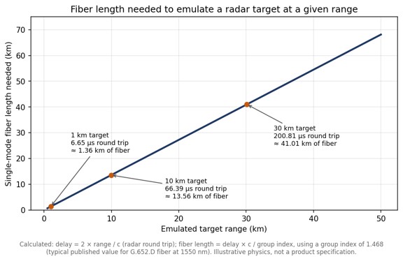
• A delay line holds back an RF signal for a precise time and is used for radar and altimeter testing, signal-path alignment, phased-array beamforming and signal processing. • The four main delay line families are coaxial cable, acoustic (SAW and BAW), digital (ADC, memory and DAC) and fiber optic. • Coax and fiber add a similar delay of roughly 4 to 5 ns per meter, but single-mode fiber loses well under 1 dB per kilometer regardless of RF frequency, while coax loss rises with length and frequency. • Emulating a radar target at 10 km needs about 66 microseconds of round-trip delay, or roughly 13.6 km of single-mode fiber. |
What is a delay line?
A delay line is a component that holds back an RF or microwave signal for a precise, known amount of time and then releases it otherwise unchanged. Delay lines are used to emulate distance in radar and altimeter testing, to align the timing of parallel signal paths, to build true-time-delay beamformers for phased arrays and to provide short-term signal memory in correlators and receivers.
In radar work the delay always represents a round trip, which makes the numbers grow quickly. A SPIE conference paper comparing microwave analog delay line technologies points out that emulating a target only 50 m away already calls for 333.33 ns of delay, because the signal has to travel out and back. For readers who want the underlying vocabulary first, a broader primer on delay lines covers the terms used throughout this comparison.
What types of delay line are available?
There are four main families of RF delay line: coaxial cable, acoustic (surface or bulk acoustic wave), digital, and fiber optic. Each creates delay in a physically different way, and that physical mechanism determines its loss, bandwidth, size and flexibility.
| Technology | How the delay is created | Main strengths | Main limitations |
| Coaxial cable | The RF signal travels through a coiled length of coax, often semi-rigid | Simple, passive, no signal conversion | Bulky at long delays; loss rises with length and frequency |
| Acoustic (SAW / BAW) | RF is converted into an acoustic wave in a piezoelectric material, which travels far slower than an electromagnetic wave | Very compact for a given delay | High insertion loss, reported above 30 dB; SAW limited to roughly 2.5 GHz |
| Digital | The signal is sampled by an ADC, held in memory and regenerated by a DAC | Delay is programmable and can be combined with synthetic Doppler or modulation | Bandwidth and spurious performance set by the converters; adds latency of its own |
| Fiber optic (ODL) | RF is modulated onto light and delayed by a chosen length of single-mode fiber | Low loss that does not change with RF frequency; delays from nanoseconds to milliseconds | Requires optical conversion, which adds noise; each delay value needs its own fiber length or a switch path |
How do coaxial delay lines compare with fiber optic delay lines?
Coax and fiber produce a similar delay per meter, around 4 to 5 nanoseconds depending on the cable dielectric, but fiber achieves it with a tiny fraction of the loss. Standard G.652.D fiber has a group index close to 1.468, which works out to roughly 4.9 ns of delay per meter, or about 4.9 microseconds per kilometer.
The difference shows up in attenuation. A microsecond of delay needs roughly 200 m of either medium. Published attenuation tables put even thick 7/8-inch hardline at about 2.1 dB per 100 feet at 2.4 GHz, which means close to 14 dB of loss over 200 m, and thinner coax several times more. The same 200 m of single-mode fiber loses well under 0.1 dB of optical power. Just as important, the fiber loss is set by the optical wavelength rather than by the RF carrier riding on it, so the fiber in a fiber optic delay line contributes the same loss at 1 GHz as at 18 GHz, while a coax delay line becomes progressively lossier as frequency rises.
Longer delays make the gap decisive. The chart below shows how much fiber a radar test needs to emulate targets at different ranges. A 10 km target already requires about 13.6 km of fiber, a length no coax delay line could realistically match.

When do acoustic or digital delay lines make more sense?
Acoustic delay lines make sense when space is tight and the signal sits below a few gigahertz, and digital delay lines make sense when the delay must change continuously or the test needs synthetic signal effects. Acoustic devices exploit the fact that a mechanical wave in a piezoelectric crystal moves far more slowly than an electromagnetic wave, so a long delay fits in a small package. The cost is high insertion loss and, for surface acoustic wave parts, an upper frequency limit of around 2.5 GHz; bulk acoustic wave technology extends the achievable delay range.
A university study of wideband delay lines for automotive radar compares these approaches for a target simulator that needed an 800 MHz bandwidth and delays tunable from 1.3 ns to 1.67 microseconds, a useful example of how bandwidth and delay range together narrow the technology choice. Fully digital delay lines take a different route: an analog-to-digital converter samples the signal, memory holds it, and a digital-to-analog converter regenerates it. That flexibility is valuable, but instantaneous bandwidth, dynamic range and spurious content all depend on the converters.
What is the difference between fixed, variable and progressive delay lines?
A fixed delay line provides one delay value, while a variable delay line lets the user switch between several delays; a progressive delay line is a variable design that combines a small set of fiber spools in different combinations to produce many more delay values than it has spools. A passive optical delay line is simply a coil of fiber cut to an exact length and needs no power; in an RF system it sits between an optical transmitter and receiver.
Progressive designs typically use cascaded optical switch matrices. Four 2×2 optical switches can select 16 different delays, and eight binary-weighted spools can produce 255 distinct non-zero combinations. Variable, progressive and passive optical delay line architectures are explained in more detail, including how dispersion compensation and optical amplification are added when delays become very long.
How should an engineer choose a delay line?
Start from the application’s frequency range and maximum delay, then check loss, noise and switching requirements against each technology. The following criteria narrow the choice quickly:
- Frequency range: acoustic devices suit lower bands, while coax and fiber cover microwave frequencies and fiber holds its loss steady across them.
- Maximum delay and resolution: delays beyond a few hundred nanoseconds favor fiber; fine, continuously adjustable steps favor digital or switched designs.
- Insertion loss and noise figure: acoustic parts lose the most signal, while optical links trade a fixed conversion loss for nearly flat loss with length.
- Signal purity: phase noise and spurious content matter for radar and altimeter testing, where the delayed signal must look exactly like a real echo.
- Switching and control: test benches often need several delay values selectable from a front panel or remotely.
For signal-purity questions in optical designs, an application note on phase noise and RF amplification in ODL systems covers how amplifier placement affects the delayed signal. For catalog-level comparison of ranges and switch configurations, fiber optic delay line hardware shows how commercial units package these options into rack-mount systems.
Frequently Asked Questions
What is a delay line used for?
A delay line holds back an RF signal for a precise time, which is used to emulate target distance in radar and altimeter testing, align signal paths, steer phased-array beams and store signals briefly for processing.
How much delay does one meter of optical fiber add?
One meter of standard single-mode fiber adds roughly 4.9 nanoseconds of delay, based on a group index of about 1.468.
Why are fiber optic delay lines preferred for long delays?
Fiber optic delay lines are preferred for long delays because single-mode fiber loses well under 1 dB per kilometer and that loss does not change with the RF frequency being delayed, while coaxial cable loss grows with both length and frequency.
What is a progressive delay line?
A progressive delay line combines a small set of fiber spools through optical switches so that many delay values can be selected; eight binary-weighted spools can produce 255 different non-zero delays.