Business Solutions
5G mmWave Testing: Why RF over Fiber Has Become the Lab Standard
Summary: As 5G networks push into the millimeter-wave (mmWave) frequency bands, the challenge of accurately testing these systems in a laboratory environment has grown dramatically. This article examines the unique testing demands of 5G FR2 mmWave devices, why traditional coaxial test setups struggle at these frequencies, and how RF over fiber technology enables more accurate, repeatable, and scalable 5G test environments. It also outlines how RFOptic’s purpose-built RFoF solutions address the needs of 5G/6G testing engineers worldwide.
The global rollout of 5G networks represents one of the most complex RF engineering challenges in telecommunications history. For the test and measurement community, it has introduced equally demanding new requirements – particularly as deployments move into the mmWave spectrum. Engineers evaluating whether their test infrastructure is ready should start with a foundational question: can your signal transport method keep up with the frequencies you are testing? Exploring rf over fiber technology is increasingly the answer that test labs are arriving at.

Understanding 5G FR2: The mmWave Challenge
5G is defined by two frequency ranges. FR1 covers the sub-7 GHz bands familiar from 4G LTE, while FR2 – often called mmWave 5G – covers bands from approximately 24.25 GHz up to 52.6 GHz in the current 3GPP standard framework, with future extensions anticipated beyond 100 GHz for 6G precursor research. These FR2 bands offer multi-gigahertz of contiguous spectrum, enabling peak data rates measured in gigabits per second and ultra-low latency performance that FR1 alone cannot deliver.
However, mmWave signals propagate very differently from sub-6 GHz RF. They are attenuated much more rapidly in air, blocked by building materials, and absorbed by the body of a device under test. This means 5G mmWave devices almost universally rely on beamformed, phased array antenna systems – integrated directly into the device – that electronically steer a narrow beam to maintain link quality.
For test engineers, this creates a significant problem: these integrated antenna arrays cannot be physically connected to a test instrument via a coaxial cable. Testing must be done over the air (OTA) – meaning the device radiates its signal in free space, and test instruments must receive and analyze the radiated field. This in turn demands anechoic or semi-anechoic chamber environments, precise positioning, and signal transport from the antenna probe in the chamber to the instrument rack outside it.
The 3GPP’s technical specifications for 5G OTA testing are detailed in the TS 38.521 and TR 38.810 documents, which outline measurement configurations for FR2 devices. 3GPP Technical Specifications provide the industry baseline against which all 5G OTA test methodologies are validated.
Why Coaxial Cable Fails the 5G FR2 Test
At sub-6 GHz frequencies, the losses introduced by a coaxial cable between a test antenna and an instrument are manageable. At 28 GHz or 39 GHz, they are not. Signal attenuation in standard coaxial cables at mmWave frequencies is dramatically higher – often 2 to 4 dB per meter or more at Ka-band frequencies, depending on cable diameter. For a test setup with antenna probes positioned several meters from the instrument, this means severe signal degradation.
The consequences are measurable and serious:
- Higher noise floor in the measurement system, reducing sensitivity and making it harder to detect weak signals from the device under test.
- Reduced dynamic range, preventing the system from characterizing both strong and weak signals in the same measurement sweep.
- Phase instability due to coax mechanical sensitivity — even bending a cable can shift its phase response, introducing errors in phase-sensitive measurements like EVM (Error Vector Magnitude).
- Impractical cable management: at mmWave frequencies, even small connectors introduce insertion losses and mechanical fragility becomes a reliability concern in frequently reconfigured test environments.
- Fundamental frequency limits of most coaxial assemblies make coverage above 40 GHz an engineering challenge requiring specialized and expensive waveguide solutions.
RF over Fiber as the 5G Test Infrastructure Standard
RF over fiber addresses the signal transport problem in 5G FR2 test environments at the fundamental level. Instead of routing the mmWave signal through coaxial cable, RFoF converts it to an optical signal immediately at the antenna probe and transports it over optical fiber to the instrument. Optical fiber has negligible attenuation in the relevant transmission windows (on the order of 0.3 dB/km), is completely immune to electromagnetic interference, and does not introduce phase errors due to bending or temperature changes.
For 5G test labs, this translates to practical advantages:
- Probe-to-instrument distances of tens of meters or more with minimal signal degradation – enabling large anechoic chambers and flexible test geometries.
- Consistent signal integrity that enables accurate, repeatable measurements across multiple test runs and different environmental conditions.
- Freedom from EMI: test chambers often house high-power amplifiers, switching equipment, and other RF sources. Fiber is immune to all of this.
- Simplified test cell design: replacing bundles of mmWave coaxial assemblies with a single fiber link dramatically reduces installation complexity.
RFOptic’s Role in 5G/6G Testing
RFOptic’s stated mission is to provide state-of-the-art RF-optical solutions with superior performance to the 5G/6G testing emerging markets. The company describes itself as a solutions provider and R&D-driven innovative manufacturing company with global coverage and extensive experience with customized solutions for the 5G testing markets.
RFOptic offers what it describes as top-notch RF-over-glass commercial off-the-shelf products for civil 5G and defense applications. Key elements of their 5G testing product line include:
- Off-the-shelf RF over fiber links covering from DC to 67 GHz in three family groups, providing frequency coverage from well below FR1 through the complete FR2 band and into mmWave territory relevant for 6G research.
- HSFDR (High SFDR) links optimized for applications where spurious-free dynamic range and signal stability are paramount – exactly the conditions required for accurate 5G OTA measurements.
- Subsystems and end-to-end solutions per customer requirements, recognizing that 5G test labs often have specific chamber dimensions, device categories, and measurement configurations that require tailored signal transport architectures.
- Remote management: all links and subsystems are managed by local or remote management interface, supporting the integration of RFoF links into automated test system software environments.
RFOptic also provides an online RFoF link calculator tool to assist test engineers in predicting link performance parameters including noise figure, gain, and dynamic range for their specific configurations – enabling accurate test system planning before hardware deployment.
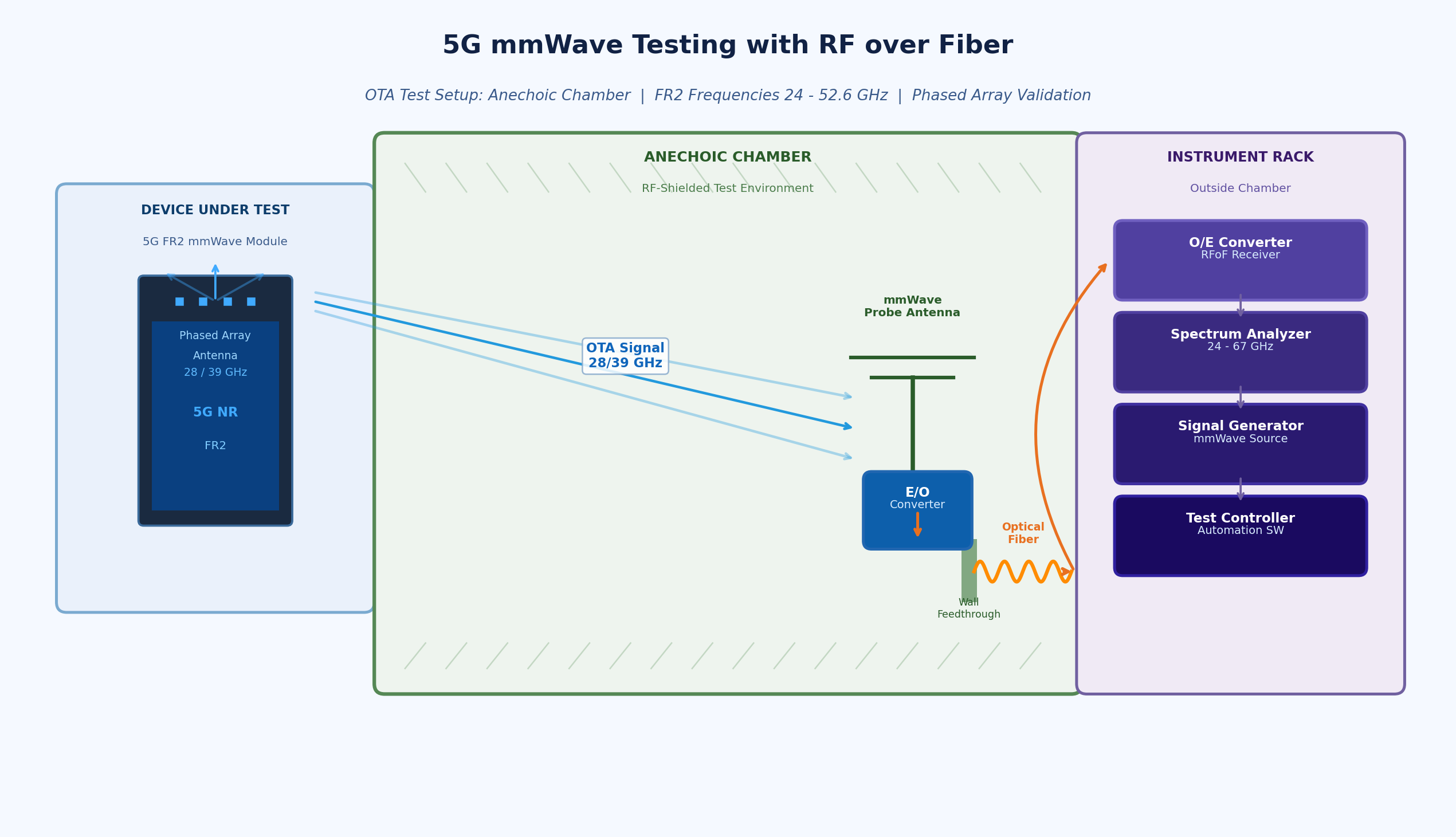
Anechoic Chambers and Remote Antenna Applications
One of the most direct 5G test applications for RFoF is the anechoic chamber setup. In this configuration, the test antenna (probe) is inside the shielded chamber, while the signal generator and analyzer are in the equipment rack outside. Connecting these requires passing the mmWave signal through the chamber wall – a location where coaxial feedthroughs introduce insertion loss, potential leakage, and EMI ingress.
RFOptic offers specific solutions for anechoic chamber applications, recognizing that this is a core use case in the 5G test environment. The optical fiber feedthrough eliminates the shield integrity problem and allows the full mmWave bandwidth to be transported without the frequency-dependent losses of coaxial alternatives.
Preparing for 6G: The Frequency Frontier
While 5G mmWave deployments are still in early phases in many markets, research and pre-standardization work on 6G has already begun at frequencies above 100 GHz – the D-band (110–170 GHz) and beyond. Test infrastructure being deployed today for 5G FR2 will increasingly need to serve as the foundation for 6G research environments.
Choosing RFoF solutions with frequency coverage well beyond the immediate 5G FR2 requirement provides a degree of future-proofing for test facilities. RFOptic’s product family, which extends to 67 GHz in its standard off-the-shelf range, positions test labs to expand measurement capability as 6G frequencies become relevant for device and system characterization.
Engineers specifying rf over fiber modules for 5G test infrastructure are therefore making a technology investment with a long useful life – particularly when the solution comes from a vendor with demonstrated capability well above the minimum required frequency and with a track record of supporting customized configurations.
Conclusion
The shift to 5G FR2 mmWave testing has fundamentally changed what test and measurement infrastructure must deliver. Signal transport between antennas and instruments across the 24–40 GHz range demands low loss, phase stability, EMI immunity, and scalability that coaxial cable cannot reliably provide. RF over fiber has become the standard solution for forward-thinking 5G test labs, and its role will only grow as the industry progresses toward 6G research frequencies.
For test engineers and lab managers evaluating their signal transport architecture, the key criteria are frequency coverage, dynamic range, phase consistency, and the availability of system-level support. Purpose-built RFoF solutions from experienced high-frequency vendors offer the complete package for today’s 5G test challenges and tomorrow’s 6G requirements.